
Page 204 - Making PIC Microcontroller Instruments and Controllers
P. 204
2OO COUI{TITG PULSE$ A PNOGNAM ABIE TACHOMEIER
c4
c5
Q6
c7
84
B5
B6
87
displavs as
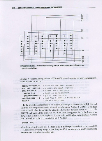
one way of $/iring lor the seven-segment
mf*i*{e$p&
display. A crment limiting resistor of 220 to 470 ohms is needed between each segment
and the conmon anode,
PoRTA=?o0000001 turn on lhe itst segnent
PORTB=%11111110 select lhe f,rs! segment
FOR X-l IO I theae are a seqmenrs
PAUSE 100 Look at each segnenr
POREB=DOREB< < 1 go lo nex! segflnent
PORIE.PORTB + 1 pu! the 1 back in PorlB bi! 0
NEXT X do lhe nexL one
In the preceding prcgram clip, we start with the segment connected to B 0 ON and
shit tfre iits one posltlon to the left wlth each iteration Adding I to PORTB replaces
the 0 in the bit after the shift to the left with a I The last iteration leaves % 1 1 1 1 1 1 1 1 in
PORTB and tums all the segments off. If we want to suppress tbe declmal poinl' we
have to aalal a line of code to place a 1 iII the affected bit afte' each iteration- Assume
that the decimal point is connected to bit 3 Adding:
PORIB.3=1;
after the shift instruction puts a 1 back at bit 3 and keeps the decimal point turned off'
The finished working piogram (see Program 15.3) uses the pulse length determining
instruction to calculate the pulse rate