
Page 219 - Making PIC Microcontroller Instruments and Controllers
P. 219
216 GREATIIIG ACCURATE II{TEBYALS WITH TIMEB$ THE METRONOMES
Here is the plan for testing the operation of Timero:
t . We will increment the value of the variable X in the jnterrupt routine. Therefore, we
will be sure we have entered and rctumed from rhe interupt routine if this value is
being inuemented,
2, We will display the value of X in the main loop. Thereforc, if we see X incremented,
the intenupts are being called and returned from wbile we are in the main loop.
3,If we see the preceding two things tating place, we will have successfully used
Timer0. It's that simple. We will be ready to use Timero in oul programs.
These first prograns for Timer0 ar€ heavily commented, so you can see exactly what
is being done. The programs that follow are less heavily commented because they are
very similarto these first programs.
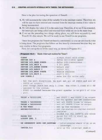
Firsl, let's set up the LCD the usual way, as shown in Program 16.1.
iUiqii!!i!!:!.-!.!!::ll Basic Interrupt routlneforTlmerl
CLETAR ; atways slart wilh clear
DEFINE OSC 4 ; defne oscillaLor speed
DEFTNE l,CD DREG PORAD ; defne LCD comeciions
DEFINE trcD DBlt 4 ; 4 bi! palh
DEFINE ICD_RSREG PORTE ; selec! regr
DEFINE I.cD RSAIT 0 ; select bit
DEFINE I"CD_EREG PORfE ; enable regisLer
DEFINE LCD EBIt ! ; enable bil
I,oW POR4E.2 ; nake 1ow for write only
set the poxt tlirections. w! nust set all of PoRrD and all of
PORTE as outputs
even though PoRTE has only 3 1ines. The other s lines will be
ignored by the systen-
PoRTc is needed because the piezo speaker is on pin 2 of this
TRTSC = %11111001 , ."a "O*t".t and PORTC.2 as output
; for the speaker md LED comecLions
IRISD = %00000000 ; seL all PORTD lines to output
TRISE = %00000000 ; seC all PORTE lines lo output
X VAR WORD ; seL up Lhe wariable
ADcoNl-%00000111 ; se! lhe Analoer-to-Digital control
; register
; needed for the 16F8774 see notes
PAUSE 500 ; pause for LCD !o slart up
LCDOm SFE, 1 ; clear screen
ON IItrIERRI'PI GOIIO INI ROUIINE ; Lells pxogram whexe to go on an
, interrupt
INrcON.5=l ; sets up the interrupt, enable
(ContinueA