
Page 224 - Making PIC Microcontroller Instruments and Controllers
P. 224
ttMEn0 227
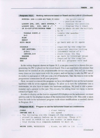
!&ffffiiwfi*g Worklng metronome based on Timen and the LAB-X1 (Continuedl
po4r'os= 208- ( ( (208-40) *a2D_v) ; the potentiomeLer
/25s)
; position value
"
raDolxt $FE, s80, m€ PorPos, ; Display the position
r.cDout $FE, sco, DEc x ," . ; display the X count
IF X>=15.15*5o/PO|IPOS THEN Lhis is ahere we add the NltipLy
by 15
EOGCI,E PORI!C.2 Coggle the speaker
x=0
ELSE
ENDIF
GOIO MAIN so back and do iL agrain
DTSAAI.E required by the conpiler
IITT-ROUTINE:
X=X+t increnent walue of x
INICON.2E0 reset/clear the flas
RESUI'E
ENABIJE
END
In the wiring diagram shown in Figure 16.3, a ten-pin connector is shown (for pro-
gramming the PIC in place) on the ciftuit board. This is an important conv€nience that
should not be omitted on any programmable device you cr€ate. You will use it many,
many times as you experim€nt with the poject, and not having to take the PIC out of
its socket to reprogram it will save you a lot of headaches. Take the time to wire in the
programmer cofirection (in all your Fojects).
Next, we need to conveft the program we have developed to run on the tachometer
hardware with its seven-segme displays. To allow us to tum the tachometer into a
metronome, we also have to make two hardware additions. We need to add a poten-
tiometer and a speaker to the card. The circuitry for adding these two items is shown
circl€d in Figure 16.3.
In order to display on the 4 seven segment LED djsplays on the tachometer, we must
add the code for the displays in place of the instructions for the LCD. This code is taken
from the code in the tachometer program (with minor modifications as needed) shown
in Progran 16.4.
Program to use the tachometer board as a metronome
CI,E'R
DEFINE OSC 4
; The fotlowing are lhe inages of the nurnbers
j s t o r e d i _ a e _ r y b e f o l e w a d o o l y r l . n 9 . T l e s d 6 - - -
o
r
i b - u s - d i l D O F I B o s e t . l ^ e I r o ' l c - r n e - c h d - g i . .
; Your wirins di1l require nunbers to suit it.
wRrrE 1999, %11111111