
Page 293 - Making PIC Microcontroller Instruments and Controllers
P. 293
294 SIIIGLE SET POIIIT COI{TROIIER W|rH NEMOTE II{HIBIT CAPABII.ITY
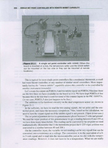
lf!lt$*q!!!i A single set point controller with inhibit. (When this
board is mounled on a box, the lemoe|aiure selter and the inhibil swilch
can be mounted on lhe box side of lhey can be mounted at remote
locations.)
This is typical for most singlc-point controllers like a residential themostat, a small
hot water heater controller, or any number of similar on/off conhollers. More impor_
"renote
t^niy haviftB the inhibit" capability allows this controller to be co trolled bJ
(remoteh).
another i strument
Let's create the outp t on PORIAs and the inhibit signal on PORTA.3 because these
arc the two lines we have available on the board as it is. We have kept PORIA4 free
j
because this is the line ihat s used for some of the counter inputs in the PIC 16F877A.
(In ourcase, PORIA5 alsojust happens to be fiee.)
The additions to the hadware circuitry on the dual temperature sensor arc shown in
Figre 27.2.
In the software, we have to rcad the two analog sigllals, the set point and the con-
trolled point, and rnake the necessary comparison. Then, based on the calculation, we
need to turn the output sigral on if the inhibit signal is not present (Open in our case )
The set point adjustment device is a potentiometer placed between 5 volts and ground.
We rcad the wr!€r position of this potertiometer to get a reading between 0 and 255 as
we have done many times before. This reading can be converted to the set point we need
mathematically. (Remember that in the metronome project the 0-255 wiper posinon was
converted to a number betwe€n 40 and 208.)
On fhe controller input, the variable we are reading can be any signal that can be
convefieal into a resistance or a voltage. The conversion is to the equivalent of a 0-
to 5-volt signal and is read into the microcontrollerjust as we did with the temper-
ature readings. However, it does not have to be a temperature What we are really