
Page 297 - Making PIC Microcontroller Instruments and Controllers
P. 297
29A SITIGLE POII{T CO TROILER WITH EEMOTF I HIBII CAPABILIIY
SET
As always, we need a rcsistance of about 5000 ohms in se es with the thermistor so
the circuit will not shof actoss the power supply by drawirg too much cuffent wher
the thermistor is at its cold extreme
In the usual case, the resistance in the circuit should be selected to match ihe ambi-
ent temperatue resistance of the thermistor' This will give a reading of 127 or the wiper
rniddle position at the ambient temperature The rcsistance can be varied to rajse ancl
lower the ambient temperature reading. The total resistance of the rcsistance and the ther_
mistor should be at lcast 5000 ohms fot most applications
The sensitivity of tbe readings wil be best if the effect of the change in resrstance ol
the thermistor is such that the range expected is apprcximately the same as the pot
valuel however, as mentioned eatlier, the total resjstance should not get below about
4k ohms to keep from overwhelming the power supply
Some other reliable method should be available to confirm that your rnstrument rs
Drovialins accurate values for the temperatures being measured'
'
OtherLvices are used in a similar way. If a device provides a voltage' the voltage
can be divided or amplified to be at a suitable level and then connected between ground
and the input poft p;. A reference voltage does not necessarily need to be connected
to the PIC. Select and connect the Vdd source to suit
BEADII{G THERMOCOUPLES
Themocouples provide ext€mely low voltages and almost no current so we have Io appfox-
imate the conditions pcvided by awheatstone bridge to rcad them Altematively' op amps
that amplify the signal can be use{] The industry pirvides a number of ICs that allow each
of the types of thermocouples to be read into a PIC{ype micrcconiroller with relative ease
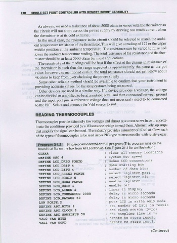
prpgfaql 2l.t Single-point controller: lull program fihis program rJns or lhF
boa; that lrts on the box ircn All Electro,lics See Figure 21 1 lofar illusiralon )
CI/EAR clear all nenory locations
DEFINE OSC 4 sysLen osc speed
DEFINE LCD DRIG PORTD define LCD connecLions
DEFINE ICD_DBIT 4 daLa slarting bit
DEFINE LCD aITS 4 nunrlcer of data bits
DEFINE I,CD RSREG PORTE sefec! regis!er Port
DEFTNE I,CD RSBIT O select resisler bi!
DEFINE LCD-EREG PORTE enable resister
DEFINE LCD-EEIIT 1
DEFINE I,CD_I.INES 2 lines in display
DEFINE LCD_CO!4MAIIDUS 2OOO delay in nicro seconds
DEFINE LCD_DAIIAUS 50 delay in nicro seconds
LOW PORIFE.z puLs lrCD in write only node
DEFINE ADC BITS A seL nuiber of birs in result
DEFINE A'C CLOCR 3 set clock source (3=rc)
DEFINE AlC SATIPLAUS 50 seL sanpLinq Line in us
1IA'.o VAR BYTE create to slore resulL
VAI,1 VAR WORD creale to slore result
(Cantinued)