
Page 307 - Making PIC Microcontroller Instruments and Controllers
P. 307
sollu4EE ,9.99
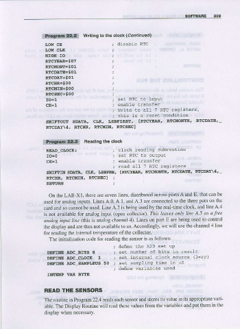
ilf.tsiliii6i*Ag,l writing to lhe clock (co't''ued)
Low cE disable RTc
t.ow cr,K
HIGH IO
RICYEIART $ 0 7
Rrc!4o!tr=g01
RTCDAI.E= S 01
R{CDI\Y=$01
RILCITR=s00
RTCMIN=90 0
RrcsEc=s00
set RTC to input
enabLe tlansfer
Write to alt 7 RTC reqriste.s,
lhis is a reset condilion
SIIIFTIIII SDATA, CLR, LSBFIRST. IRICYE]AR. RTCIION:rH, RECDATE,
RTCDAY\4, RTCHR. RTCMIN? RTCSEC]
iilaai$grlU?1i{: Beadins the clock
RE]A.D-CI,OCR : crock xeadinq subrouline
se! RTc to outpuL
enable Lransfer
read all ? RTC regislers
SSIFTIN SDAEA, CIl(, I,SEFRE , IRTCYE]AR, RITq{OAIrIII, RIICDATE' R1IDIY\4,
RTCIIR, RTCMTNI RTCSEC] ;
RTTI'RN
On the LAB Xl, there are seven lines, distributed across ports A and E, that car be
used for analog inputs. Lines A.0, A.1, and A.3 are conneoted lo the three pots on the
card and so canrot be used. LineA.2 isbeing used by the real-iime clock' andlineA 4
is not available for analog input (open collector) This leaves onlJ line A 5 as a Iree
a aloe itlput line (.Ihis is analog channel 4). Lines on port E are being used to control
the display and are thus notavailable to us.Accordingly. we will use ihe channel4line
for teading the inlernal temperature of the collector
js
The initialization code for reading the sensor as foilows:
; define rhe A2D ser uP
DEFTNE aDC-BI!S 8 ; se! nuniLer of birs in result
DEFINE aDc-ctncB 3 ; sel internal cLock source (3=rc)
DEFINE aDc-sAt{PLsus 50 , set sanpling lime in us
; denne variabtes used
INTEMP VAR EYTE
READ IHE SEI{SORS
The routine in Program 22.4 reads each sensor and stores its value in its appropriate van-
able. The Display Routine will read these values ftolrr the varjables and put them in the
display when necessary.