
Page 34 - Making PIC Microcontroller Instruments and Controllers
P. 34
PENIPHEBAL FEATUFES 23
Peripheral Features
The lbllowing are pefipheral fealures ofthc l6F877A Microcoruollcr:
s Tiner0: 8 bil timer/counter with 8 bit prcscalar.
a Timerl: 16 bit tinrer/countef vrith prcscalar (Il can be incfemented during slcep via
an external cryslal/clock.)
x Tiner2: s-bil dmer/countcr with an 8-bii period rcgistcr. prescrlar, and postscalar
e Two PWM modules (rnaximum resolution is 10 bils)
a l0 bit multichannel analog to digital converer
a Synchronous serial po( (SSP)
x Univcrsal synchronous asynchronous receivef transmitter (USART)
a Parallcl slave port (PSP) 8 bits wide
I Brown out dctcction circuitfy for Brown out rcscl (BOR)
This MCU is dcscrjbed in pfofuse detail h a 220 page datasheet you can do\\nload
fron the Microchip Web site at no charge. The datashcel is a PDF documcnt thal yox
should have availablc to you at all iimes (maybe, elcn opcn. ir its own window. rcady
for i mmediate access). whcncvcryou arcpfogramming thc l6FE77A. The sofiwarcyou
nccd in orderto read (butnotwrilc) PDF files is also availablealno charge on the Web.
You should have a copy of the lalesl vcrsion (9) of this very usciul softwarc (Adobe
Reader) on your compuier
We will nol covcf the entiie 220-page datashcc! in these exercises. but thc most com-
thc oncs relevant to the LAB X 1 and those
nonly used lcalures of the MCU (espe{-ially
needed for our insLrumcnls Aftefdoirg thc cxcrcises,
and controllers) will bc djscussed-
you should be comlbrlablc with reading the datasheel and linding the infornalion ]'ou
nccd to get youf wol'k done.
ln our parlicular case, on the LAB X I board, the MCU is alrcady connected to the
ilens on the borrd. Therefore. ifyou wal! to use the LAB-XI lbr your own hafdwarc
erperinents. you mlrsl use the MCU pins in a way that is compatible wilh lhe compo-
nents that are alrcady connecied to ihem. Oflen (imcs. even though a pin is bcirg used
in the LAB X1 circui!ry, you can drive something clsc with it wilhout adlerscly aftect'
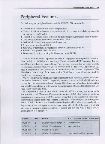
ing your experiment (dcpcnding on the load beirg ,rddcd). The following is a list you
can refer to in order to quickly dclcnnine ifthe pin 1d porl you \lant io use is tiee. or
discovd how it is being used.
PORTA PIN* USAGE PORTA HAS ONLY SX EXTEFNAL PINS
PORTA.O 2 5K ohm Potentiomeier
POBTA,l 3 5K ohm Polenliomeler L4emory chips
PORTA-2
POBTA.3 5 5K ohm Polent orneter ljsed by clock chips, memory