
Page 80 - Making PIC Microcontroller Instruments and Controllers
P. 80
7o CONTROI.LII{G THE OUTPUT AI{D FEADING THE IIIPUT
TNIS LINE IS MADE LOW
BO
W RING FOROTHER KEYS HAS BEEN
OM]TTEDTO MAKE T EASIEBTO
FEAD SCH EI\,IATIC FOR JUST ROW 1
THESE LINES HAVE BEEN PULLED HIGH
VERYWEAKLY INTEBNALLYANDW LL BE
CI] ECKED TO SEE WHiCH ONEGOES
LOWWHEN A BUfiON IS PRESSED
B4
B6
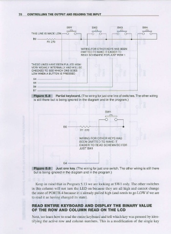
ilFiCillo:ltiEl:: Panial keyboard. (The wiring for jusl one ne ol switches. The olher wiing
is sl llthere bul is beirg ignored in lhe diagram and in lhe program.)
WIRING FOF OTHEB KEYS HAS
MAKE T
BEEN OMITTEDTO
FOFI
EAS EB TO FIEAD SCHEMATIC
JUST SW1
94
::llldilt(lli9lli Just one key. (The w ng forjust one switch.The olherwiring is stilllhere
but is be ng gnored in the diagram and n the program.)
Keep in mind that in Program 5.13 we are looking at SWl only. The other switches
in this column will not turn the LED on because they are all high and cannot changc
the statc ofPORTB.4 because it is already pulled high (and needs to goLOWif we are
to read il as having changed lts siate).
READ EI{TIRE KEYBOABD AI{D DISPI-AY THE BINARY VALUE
OFTHE ROWA D COLUIUN BEAD OI{ THE LCD
Next, we learn how to read the entire keyboard and tell wlrich key was pressedby iden
tib,ing the active row and column numbers. This is a modification of the single key