
Page 85 - Making PIC Microcontroller Instruments and Controllers
P. 85
READ OIIE POTEI{TIOMETEF 75
AI{D DISPIAY |TS A.B|T VALUE OII LCD
wiper. This gives a reading between 0 and 255 (in s-bir resolution). It rloes not tell us any_
thing abont the rcsistance of the potentiometet only the relatjve position of the wiper
js
will rcad/use the pof closest to the edge ofrhe board. This pot connected Io line
,We
PORTA.o, which is pin2 of the MCU.
_ -A-to Dconve$ions are controlled by the ADCON0 and ADCONI rcgjsters, and the
16F877A has !o be in analog mode for the relative pins fbr A_to D co;versions to be
possible.
Setting the birs in ADCON0. (See page l of the datasheet.)
Bits ? and 6 control the clock/oscillator to be used. Ser these both to 1.
Bits 5 to 3 select which chamejs are to be used in the conversions; set to 000 for
PORTA.O.
Bit 2 cleared when the conversion is completed. Set it to I to starr the conversion.
Bit I tgnorcd tn A,/D conver\'onr. Sel ir ro 0
Bit 0 controlsA-to D conversions. Setit to I to enable A-ro-D conversions.
When the conversion is completed, the result will be placed in ADRESH andADRESL.
The^format of how this is done depends on how the result is set up with rcgister
ADCONl.
ADCONI needs bit 7 to be set to 0 to make the 8_bjt rcsult appefi in ADRXSH and
bit 2 needs to be set to I to select potentiometer 0 and set the proper reference voltages.
See page I 1 2 of the datasheet.
So we set ADCONo ro 7.1100000 t ro set p for reading PORTA.0.
And we setADCON1 ro q,00000010.
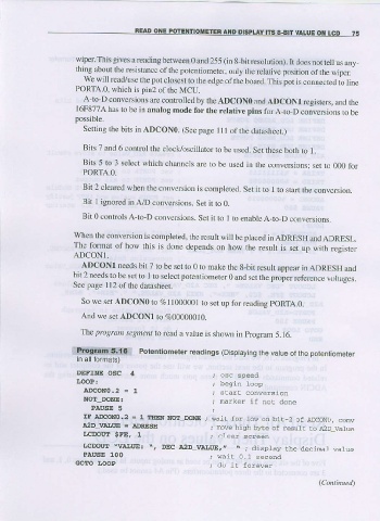
5.16.
The prcgram segment b read a value is shown in program
iit|iinliii{$m; Polentiometer readings (Disptaying vaiue of lhe potentiometer
the
in all formats)
DEFINE OSC 4
IJOOP !
ADCONo.2 = 1
NOT DONE: ; marker if not done
PAI'SE 5
IF ADCO!IIo.2 = 1 IIIEN ArcE_DoNE ; wai! for 1ow on bir 2 of AICoNO, conv
A2D r|Al,UE = ADRESE
; rcve hish bybe of resul! ro A2D_Va1ue
LCDOIIT SFE, 1
; cleai screen
LCDOIIT \VAlJttE: ., DEC t2D-VALtrE,. \. ; display the decinal vatue
PAUSE 100
; vail 0-1 second
GOTO IOOP