
Page 312 - Making things move_ DIY mechanisms for inventors, hobbyists, and artists
P. 312
Chapter 10 Projects 289
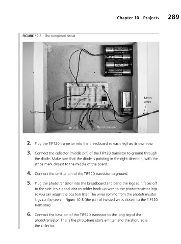
FIGURE 10-8 The completed circuit
Motor
wires
Switch
IR LED Phototransistor
2. Plug the TIP120 transistor into the breadboard so each leg has its own row.
3. Connect the collector (middle pin) of the TIP120 transistor to ground through
the diode. Make sure that the diode is pointing in the right direction, with the
stripe mark closest to the middle of the board.
4. Connect the emitter pin of the TIP120 transistor to ground.
5. Plug the phototransistor into the breadboard and bend the legs so it faces off
to the side. It’s a good idea to solder hook-up wire to the phototransistor legs
so you can adjust the position later. The wires coming from the phototransistor
legs can be seen in Figure 10-8 (the pair of twisted wires closest to the TIP120
transistor).
6. Connect the base pin of the TIP120 transistor to the long leg of the
phototransistor. This is the phototransistor’s emitter, and the short leg is
the collector.