
Page 317 - Managing Global Warming
P. 317
Hydropower 277
Surge tank
Before 1950
Supply tunnel
Penstock
Surge
chamber
Headrace tunnel
Steel - lined
1950–60
Access Shaft
Tailrace tunnel
From 1960 on
Pressure shaft
Unlined
From 1975 on
Closed, unlined surge
chamber with air cushion
Unlined high - pressure tunnel
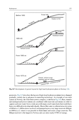
Fig. 8.5 Development of general layout for high-head hydropower plants in Norway [10].
penstocks. Fig. 8.5 show how the layout of high-head hydropower plants have changed
gradually, mainly due to advances in tunneling technology. An example of one such
system in Norway, the Ulla-Førre power complex, is shown in Fig. 8.6. Here, tunnels
and underground power stations are combined with reservoirs and intakes in order to
capture and store water from a wide area with many small watersheds that would have
been verydifficulttodevelopindividually.Most ofthe water iscollectedatanelevation
of 600ma.s.l. (600m above sea level) and pumped up to a very large reservoir (Bla ˚sjø)
at 1000ma.s.l. where it was possible to build dams and create a huge reservoir. The
Bla ˚sjø reservoir is the largest in Norway and can store nearly 8TWh of energy.