
Page 245 - Manufacturing Engineering and Technology - Kalpakjian, Serope : Schmid, Steven R.
P. 245
224 Chapter 9 Composite Materials: Structure, General Properties, and Applications
fiber-reinforced packaging tape is when pulled in tension, yet
how easily it can split when pulling in the width direction.
Because it is an engineered material, a reinforced plastic
part can be given an optimal configuration for a specific serv-
ice condition. For example, if the part is to be subjected to
forces in different directions (such as in thin-walled, pressur-
ized vessels), (a) the fibers can be criss-crossed in the matrix,
or (b) layers of fibers oriented in different directions can be
built up into a laminate having improved properties in more
than one direction. (See #lament winding, Section 19.13.3.)
Also, a composite flywheel rotor has been produced using a
(H) (D)
special weaving technique in which the reinforcing fibers (E-
glass) are aligned in the radial direction as well as in the hoop
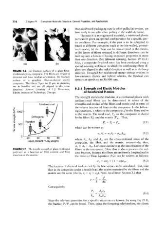
FIGURE 9.6 (a) Fracture surface of a glass fiber-
direction. Designed for mechanical-energy storage systems in
reinforced epoxy composite. The fibers are 10 /.tm in
diameter and have random orientation. (b) Fracture low-emission electric and hybrid vehicles, the flywheel can
surface of a graphite fiber-reinforced epoxy operate at speeds up to 50,000 rpm.
composite. The fibers, 9 um to 11 /rm in diameter,
are in bundles and are all aligned in the same
direction. Source: Courtesy of L.]. Broutman, 9.3.l Strength and Elastic Modulus
Illinois Institute of Technology, Chicago. of Reinforced Plastics
The strength and elastic modulus of a reinforced plastic with
unidirectional fibers can be determined in terms of the
Unidirectional strengths and moduli of the fibers and matrix and in terms of
the volume fraction of fibers in the composite. In the follow-
1000 ' \»r ing equations, c refers to the composite, f to the fiber, and fn
to the matrix. The total load, PC, on the composite is shared
\ r
Orthogonal
Random by the fiber (Pf) and the matrix (Pm). Thus, (9.1)
P, = P) + Pm,
which can be written as
GCA, = WA, + .fmA,,,, (9.2)
O 2|O 4|O 6|0 8|O where AC, Af, and Am are the cross-sectional areas of the
Glass content (% by weight)
composite, the fiber, and the matrix, respectively; thus,
AC = Af + Am. Let’s now denote x as the area fraction of the
fibers in the composite. (Note that x also represents the vol-
ume fraction, because the fibers are uniformly longitudinal in
the matrix.) Then Equation (9.2) can be written as follows:
rr, = xo'f + (1 - x)0°,,,. (9.3)
The fraction of the total load carried by the fibers now can be calculated. First, note
that in the composite under a tensile load, the strains sustained by the fibers and the
matrix are the same (that is, ec = ef = em). Next, recall from Section 2.2 that
_2_L
e E AE'
Consequently,
3it=@ (94)
Pm Amer,” '
Since the relevant quantities for a specific situation are known, by using Eq. (9.1),
the fraction Pf/PC can be found. Then, using the foregoing relationships, the elastic
Q-"DHI
Te fro;
(MPa)
strength
nsile
w-
9.5¢
gai
"1
#9 ,_..
D2->'
er-""'
1'Dm,_l
35?
Egg'
?<Oe.
“K
9-3
53%
ya
CT
OO
Q*-Pi
2%
Q2
""1’
gin
ta?
$2
U-rr:
Qin.