
Page 289 - 04. Subyek Engineering Materials - Manufacturing, Engineering and Technology SI 6th Edition - Serope Kalpakjian, Stephen Schmid (2009)
P. 289
268 Chapter 11 Metal-Casting Processes and Equipment
\ Pattern ~
Coated
sand
Coated Sand Investment
Pattern
Coated Dump box
sand
1. Pattern rotated 2. Pattern and dump 3. Pattern and dump box
and clamped to dump box box rotated in position for the investment
'/0
Shell
_g Shells
f
Excess Sandor
coated sand Adhesive C|ampS metal beads
4. Pattern and shell 5. Mold halves joined together 6. l\/lold placed in flask
removed from dump box and metal poured
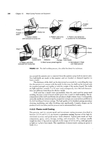
FIGURE l l.9 The shell-molding process, also called the dump-box technique.
ens around the pattern and is removed from the pattern using built-in ejector pins.
Two half-shells are made in this manner and are bonded or clamped together to
form a mold.
The thickness of the shell can be determined accurately by controlling the time
that the pattern is in contact With the mold. In this way, the shell can be formed with
the required strength and rigidity to hold the Weight of the molten liquid. The shells
are light and thin-usually 5 to 10 mm-and consequently, their thermal character-
istics are different from those for thicker molds.
Shell sand has a much lovver permeability than the sand used for green-sand
molding, because a sand of much smaller grain size is used for shell molding. The de-
composition ofthe shell-sand binder also produces a high volume of gas. Consequently,
unless the molds are vented properly, trapped air and gas can cause serious problems in
the shell molding of ferrous castings. The high quality of the finished casting can reduce
cleaning, machining, and other finishing costs significantly. Complex shapes can be
produced with less labor, and the process can be automated fairly easily.
I l.2.3 Plaster-mold Casting
This process, and the ceramic-mold and investment casting processes described in
Sections 11.2.4 and 11.3.2, are known as precision casting, because of the high di-
mensional accuracy and good surface finish obtained. Typical parts made are lock
components, gears, valves, fittings, tooling, and ornaments. The castings usually
Weigh less than 10 kg and are typically in the range of 125 to 250 g, although parts
as light as 1 g have been made. The capabilities of plaster-mold casting are given in
Table 11.2.