
Page 663 - 04. Subyek Engineering Materials - Manufacturing, Engineering and Technology SI 6th Edition - Serope Kalpakjian, Stephen Schmid (2009)
P. 663
Chapter 23 Machining Processes: Turning and Hole Making
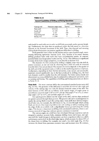
TABLE 23.I0
General Capabiiities of Drilling and Bering Operations
Hole depth/diameter
Cutting tool Diameter range (mm) Typical Maximum
Twist drill 0.5-150 8 50
Spade drill 25-150 30 100
Gun drill 2-50 100 300
Trepanning tool 40-250 10 100
Boring tool 3-1200 S 8
and should be used with care in order to drill holes accurately and to prevent break-
age. Furthermore, the chips that are produced within the hole move in a direction
opposite to the forward movement of the drill. Thus, chip disposal and ensuring
cutting-fluid effectiveness can present significant difficulties in drilling.
Drills generally leave a hurr on the bottom surface upon breakthrough, neces-
sitating deburring operations (Section 26.8). Also, because of its rotary motion,
drilling produces holes with walls that have circumferential marks. In contrast,
punched holes have longitudinal marks (see Fig. 16.5a). This difference is significant
in terms of the hole’s fatigue properties, as we describe in Section 33.2.
The diameter of a hole produced by drilling is slightly larger than the drill di-
ameter (oz/ersize), as one can note by observing that a drill can easily be removed
from the hole it has just produced. The amount of oversize depends on the quality of
the drill and of the equipment used, as well as on the machining practices employed.
Furthermore, depending on their thermal properties, some metals and nonmetallic
materials expand significantly due to the heat produced by drilling; thus, the final
hole diameter could be smaller than the drill diameter. For better surface finish and
dimensional accuracy, drilled holes may be subjected to subsequent operations, such
as rearning and honing. The capabilities of drilling and boring operations are shown
in Table 23.10.
Twist Drill. The most common drill is the conventional standard-point twist drill
(Fig. 23.19a). The geometry of the drill point is such that the normal rake angle and
velocity of the cutting edge vary with the distance from the center of the drill. The
main features of this drill are as follows (with typical ranges of angles given in
parentheses): (a) point angle (118° to 135°), (b) lip-reliefangle (7° to 15°), (c) chisel-
edge angle (125° to 135°), and (d) helix angle (15° to 30°).
Two spiral grooves (flutes) run the length of the drill, and the chips produced
are guided upward through these grooves. The grooves also serve as passageways to
enable the cutting fluid to reach the cutting edges. Some drills have internal longitu-
dinal holes (see, for example, the drill shown in Fig. 23.22a) through which cutting
fluids are forced, thus improving lubrication and cooling as well as washing away
the chips. Drills are available with a chip-breaker feature ground along the cutting
edges. This feature is important in drilling with automated machinery, where a con-
tinuous removal of long chips without operator assistance is essential.
The various angles on a drill have been developed through experience and are
designed to produce accurate holes, minimize drilling forces and torque, and opti-
mize drill life. Small changes in drill geometry can have a significant effect on a drill’s
performance, particularly in the chisel-edge region, which accounts for about 50% of
the thrust force in drilling. For example, too small a lip relief angle (Fig. 23.19a)
increases the thrust force, generates excessive heat, and increases wear. By contrast,