
Page 109 - Marine Structural Design
P. 109
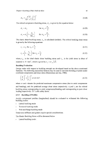
Chapter 4 Scantling of Ship’s Hulls &Rules                             85


                                                                                      (4.28)

                 The critical compressive buckling stress,  e,, is given by the equation below:


                                                                                      (4.30)

                 The elastic shear buckling stress, ze , is calculated similarly. The critical buckling shear stress
                 is given by the following equations:
                                    z
                      z,  = ref for ref < 2                                           (4.31)
                                    2

                                                                                      (4.32)

                 where, rei, is the ideal elastic shear buckling stress and z,  , is the yield  stress in  shear of
                 material in N / mm2 , which is given by: ry = o /& .

                 Buckling Evaluation
                 Design codes with respect to buckling strength are developed based on the above mentioned
                 formulae. The following interaction formula may be used to calculate buckling of plates under
                 combined compression and shear stress (Bannerman and Jan, 1980):

                      ($1 +[tJ 51.OlS.F                                              (4.33)

                 where e and zdenote the predicted maximum compressive stress (due to axial compression
                 and bending), and  the predicted  average shear stress respectively. a,and  z,  are the critical
                 buckling stress corresponding to axial compressionhending and corresponding to pure shear
                 loading respectively. S. F. is the safety factor.

                 4.5.5  Buckling of Profiles
                 Axially compressed profiles  (longitudinal) should be  evaluated to  withstand the  following
                 buckling modes:
                    Lateral buckling mode
                    Torsional buckling mode
                    Web and flange buckling mode
                 Transverse stiffeners and girders require special considerations.
                 The Elastic Buckling Stress will be discussed below.
                    Lateral buckling mode: