
Page 143 - Marine Structural Design
P. 143
Chapter 6 qffshore Structural Analysis 119
Modeling for Ultimate Strength Analysis
A finite element analysis may be conducted to calculate global longitudinal stresses and global
shear stress. For turreted FPSOs, it is necessary to predict the stress distribution around the
openings, in particular at the deck and bottom, and at the ends of longitudinal strength
elements.
All relevant variations in tank filling should be considered in the analysis and reflected in the
Operation Manual. The following stress components can be found from the FEM analysis:
Local transverse and longitudinal stresses
Transverse stresses in web frames
Double shell and double bottom stresses
Local shear stresses in panels
The combination of global and local stresses should account for actual stress directions and
phases. However, if phase information is limited or uncertain, the maximum design value for
Underme a buc#Ing code
chedc oreadl Indlwidual etlrrmsd
plate fldd hchldlna aI stress
Components and relewmt lalard
pressure COmPO~IS
(from both *des of the plate Rdd)
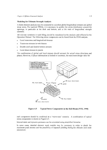
Figure 6.5 Typical Stress Components in the Hull Beam (NTS, 1998)
each component should be combined as a ‘worst-case’ scenario. A combination of typical
stress components is shown in Figure 6.5.
Internal static and dynamic pressures can be calculated using simplified formulas.
In some cases, detailed element mesh models may be necessary in order to check the
maximum peak stresses and the possibility of repeated yielding during the ultimate limit-state
assessment.