
Page 155 - Marine Structural Design
P. 155
Chapter 7 Limit State Design of qffshore Structures 131
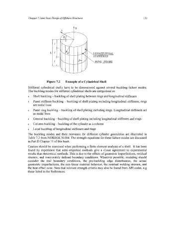
Figure 7.2 Example of a Cylindrical Shell
Stiffened cylindrical shells have to be dimensioned against several buckling failure modes.
The buckling modes for stiffened cylindrical shells are categorized as:
Shell buckling - buckling of shell plating between rings and longitudinal stiffeners
Panel stiffener buckling - buckling of shell plating including longitudinal stiffeners, rings
are nodal lines
Panel ring buckling - buckling of shell plating including rings. Longitudinal stiffeners act
as nodal lines
General buckling -buckling of shell plating including longitudinal stiffeners and rings
Column buckling - buckling of the cylinder as a column
Local buckling of longitudinal stiffeners and rings
The buckling modes and their relevance for different cylinder geometries are illustrated in
Table 7.2 from NORSOK N-004. The strength equations for these failure modes are discussed
in Part II Chapter 11 of this book.
Caution should be exercised when performing a finite element analysis of a shell. It has been
found by experience that semi-empirical methods give a closer agreement to experimental
results than theoretical methods. This is due to the effects of geometric imperfections, residual
stresses, and inaccurately defined boundary conditions. Wherever possible, modeling should
consider the real boundary conditions, the pre-buckling edge disturbances, the actual
geometric imperfections, the non-linear material behavior, the residual welding stresses, and
the heat effect zone. Note that relevant strength criteria may also be found from API codes, e.g.
those listed in the References.