
Page 340 - Marks Calculation for Machine Design
P. 340
P1: Sanjay
January 4, 2005
Brown˙C08
Brown.cls
322
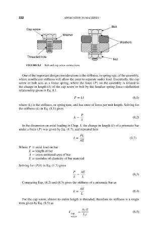
Cap screw 15:14 APPLICATION TO MACHINES Bolt
Washer
Washers
Threaded hole
Nut
FIGURE 8.1 Bolt and cap screw connections.
One of the important design considerations is the stiffness, or spring rate, of the assembly,
where insufficient stiffness will allow the joint to separate under load. Essentially, the cap
screw or bolt acts as a linear spring, where the force (P) on the assembly is related to
the change in length (δ) of the cap screw or bolt by the familiar spring force—deflection
relationship given in Eq. 8.1.
P = kδ (8.1)
where (k) is the stiffness, or spring rate, and has units of force per unit length. Solving for
the stiffness (k) in Eq. (8.1) gives
P
k = (8.2)
δ
In the discussion on axial loading in Chap. 1, the change in length (δ) of a prismatic bar
under a force (P) was given by Eq. (1.7), and repeated here
PL
δ = (1.7)
AE
Where P = axial load on bar
L = length of bar
A = cross-sectional area of bar
E = modulus of elasticity of bar material
Solving for (P/δ) in Eq. (1.7) gives
P AE
= (8.3)
δ L
Comparing Eqs. (8.2) and (8.3) gives the stiffness of a prismatic bar as
AE
k = (8.4)
L
For the cap screw, almost its entire length is threaded; therefore its stiffness is a single
term given by Eq. (8.5) as
A T E
k = (8.5)
cap L T
screw