
Page 350 - Marks Calculation for Machine Design
P. 350
P1: Sanjay
January 4, 2005
15:14
Brown.cls
Brown˙C08
APPLICATION TO MACHINES
332
or rearranging gives
F proof = S proof A T (8.25)
The proof strength (S proof ) is the maximum allowable stress in the bolt before a permanent
set is developed. This occurs at approximately 90 percent of the yield strength (S y ) of the
bolt material. Values for the quantities in Eqs. (8.24) and (8.25) are available in references,
such as Marks’ Standard Handbook for Mechanical Engineers. If the proof strength is not
available, then use a value of 85 percent of the yield strength of the material.
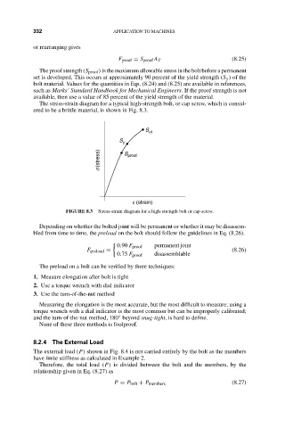
The stress-strain diagram for a typical high-strength bolt, or cap screw, which is consid-
ered to be a brittle material, is shown in Fig. 8.3.
S ut
S y
s (stress) S proof
e (strain)
FIGURE 8.3 Stress-strain diagram for a high-strength bolt or cap screw.
Depending on whether the bolted joint will be permanent or whether it may be disassem-
bled from time to time, the preload on the bolt should follow the guidelines in Eq. (8.26).
0.90 F proof permanent joint
F preload = (8.26)
0.75 F proof disassemblable
The preload on a bolt can be verified by three techniques:
1. Measure elongation after bolt is tight
2. Use a torque wrench with dial indicator
3. Use the turn-of-the-nut method
Measuring the elongation is the most accurate, but the most difficult to measure; using a
torque wrench with a dial indicator is the most common but can be improperly calibrated;
and the turn-of-the-nut method, 180 beyond snug-tight, is hard to define.
◦
None of these three methods is foolproof.
8.2.4 The External Load
The external load (P) shown in Fig. 8.4 is not carried entirely by the bolt as the members
have finite stiffness as calculated in Example 2.
Therefore, the total load (P) is divided between the bolt and the members, by the
relationship given in Eq. (8.27) as
P = P bolt + P members (8.27)