
Page 358 - Marks Calculation for Machine Design
P. 358
P1: Sanjay
January 4, 2005
15:14
Brown.cls
Brown˙C08
APPLICATION TO MACHINES
340
Cone angle a
t middle
L /2
t 1 grip L grip
t 2
h
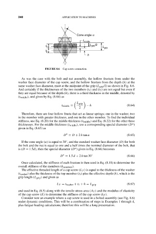
FIGURE 8.6 Cap screw connection.
As was the case with the bolt and nut assembly, the hollow frustum from under the
washer face diameter of the cap screw, and the hollow frustum from the depth (h) at the
same washer face diameter, meet at the midpoint of the grip (L grip /2) as shown in Fig. 8.6.
And certainly if the thicknesses of the two members (t 1 ) and (t 2 ) are not equal but even if
they are equal because of the depth (h), there is a third thickness in the middle, denoted by
(t middle ), and given by Eq. (8.64) as
L grip
t middle = − h (8.64)
2
Therefore, there are four hollow frusta that act as linear springs; one in the washer, two
in the member with greater thickness, and one in the other member. To find the individual
stiffness, use Eq. (8.20) for the middle thickness (t middle ) and Eq. (8.22) for the other three
thicknesses. For the middle thickness (t middle ), use a corresponding special diameter (D*)
given in Eq. (8.65) as
∗
D = D + 2 h tan α (8.65)
◦
If the cone angle (α) is equal to 30 , and the standard washer face diameter (D) for both
the bolt and the nut is equal to one and a half times the nominal diameter of the bolt, that
is (D = 1.5d), then the special diameter (D*) given in Eq. (8.66) becomes
∗
D = 1.5 d + 2 h tan 30 ◦ (8.66)
Once calculated, the stiffness of each frustum is then used in Eq. (8.18) to determine the
overall stiffness of the members (k members ).
The effective threaded length of a cap screw (L T ) is equal to the thickness of the washer
(t washer ) plus the thickness of the top member (t 1 ) plus the effective depth (h), which is the
grip length (L grip ) and given as
L T = t washer + t 1 + h = L grip (8.67)
and used in Eq. (8.5) along with the tensile-stress area (A T ) and the modulus of elasticity
of the cap screw (E) to determine the stiffness of the cap screw (k T ).
Consider now an example where a cap screw is used in a bolted assembly (see Fig. 8.6)
under dynamic conditions. This will be a combination of steps in Examples 1 through 4,
plus fatigue loading calculations; therefore this will be a long presentation.