
Page 200 - Master Handbook of Acoustics
P. 200
area.
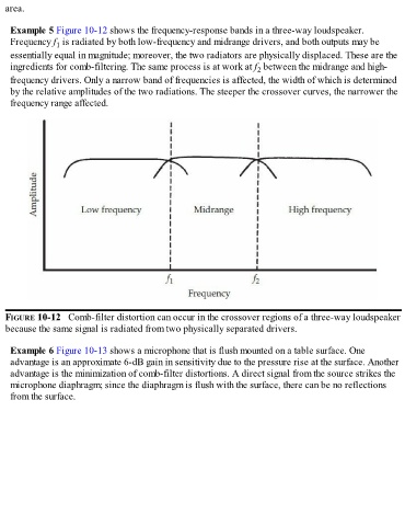
Example 5 Figure 10-12 shows the frequency-response bands in a three-way loudspeaker.
Frequency f is radiated by both low-frequency and midrange drivers, and both outputs may be
1
essentially equal in magnitude; moreover, the two radiators are physically displaced. These are the
ingredients for comb-filtering. The same process is at work at f between the midrange and high-
2
frequency drivers. Only a narrow band of frequencies is affected, the width of which is determined
by the relative amplitudes of the two radiations. The steeper the crossover curves, the narrower the
frequency range affected.
FIGURE 10-12 Comb-filter distortion can occur in the crossover regions of a three-way loudspeaker
because the same signal is radiated from two physically separated drivers.
Example 6 Figure 10-13 shows a microphone that is flush mounted on a table surface. One
advantage is an approximate 6-dB gain in sensitivity due to the pressure rise at the surface. Another
advantage is the minimization of comb-filter distortions. A direct signal from the source strikes the
microphone diaphragm; since the diaphragm is flush with the surface, there can be no reflections
from the surface.