
Page 281 - Master Handbook of Acoustics
P. 281
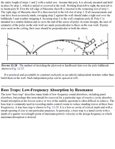
the entire length of strips 1 and 2 with a radial saw. Assume that poly A is already mounted and held
  in place by strip 1, which is nailed or screwed to the wall. Working from left to right, the next job is
  to mount poly B. First the left edge of Masonite sheet B is inserted in the remaining slot of strip 1.
  The right edge of Masonite sheet B is then inserted in the left slot of strip 2. If all measurements and

  cuts have been accurately made, swinging strip 2 against the wall should make a tight seal over the
  bulkheads 3 and weather stripping 4. Securing strip 2 to the wall completes poly B. Poly C is
  mounted in a similar fashion and so on to the end of the series of polys. In some designs, the axes of
  symmetry of the polys on the side wall are made perpendicular to those on the rear wall. If polys
  were used on the ceiling, their axes should be perpendicular to both the others.


   FIGURE 12-28   The method of stretching the plywood or hardboard skin over the poly bulkheads
   shown in Fig. 12-27.


      It is practical and acceptable to construct each poly as an entirely independent structure rather than
  build them on the wall. Such independent polys can be spaced at will.


  Bass Traps: Low-Frequency Absorption by Resonance

  The term “bass trap” describes many kinds of low-frequency sound absorbers, including panel
  absorbers, but perhaps this term should be reserved for a particular type of reactive cavity absorber.
  Sound absorption at the lowest octave or two of the audible spectrum is often difficult to achieve. The
  bass trap is commonly used in recording studio control rooms to reduce standing waves at these bass

  frequencies. A true bass trap is shown in Fig. 12-29. It is a box or cavity of critical depth and with a
  mouth opening of size to suit particular purposes. In particular, a bass trap is a tuned cavity with a
  depth of a quarter wavelength (point of maximum particle velocity) at the design frequency at which
  maximum absorption is desired.