
Page 271 - Mastering SolidWorks
P. 271
|
understanding Fillet tyPes 243
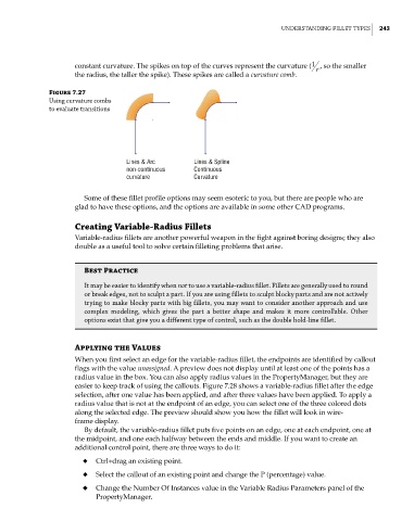
constant curvature. The spikes on top of the curves represent the curvature ( 1 r , so the smaller
the radius, the taller the spike). These spikes are called a curvature comb.
Figure 7.27
using curvature combs
to evaluate transitions
Lines & Arc Lines & Spline
non-continuous Continuous
curvature Curvature
Some of these fillet profile options may seem esoteric to you, but there are people who are
glad to have these options, and the options are available in some other CAD programs.
Creating Variable-Radius Fillets
Variable-radius fillets are another powerful weapon in the fight against boring designs; they also
double as a useful tool to solve certain filleting problems that arise.
Best Practice
it may be easier to identify when not to use a variable-radius fillet. Fillets are generally used to round
or break edges, not to sculpt a part. if you are using fillets to sculpt blocky parts and are not actively
trying to make blocky parts with big fillets, you may want to consider another approach and use
complex modeling, which gives the part a better shape and makes it more controllable. other
options exist that give you a different type of control, such as the double hold-line fillet.
Applying the Values
When you first select an edge for the variable-radius fillet, the endpoints are identified by callout
flags with the value unassigned. A preview does not display until at least one of the points has a
radius value in the box. You can also apply radius values in the PropertyManager, but they are
easier to keep track of using the callouts. Figure 7.28 shows a variable-radius fillet after the edge
selection, after one value has been applied, and after three values have been applied. To apply a
radius value that is not at the endpoint of an edge, you can select one of the three colored dots
along the selected edge. The preview should show you how the fillet will look in wire-
frame display.
By default, the variable-radius fillet puts five points on an edge, one at each endpoint, one at
the midpoint, and one each halfway between the ends and middle. If you want to create an
additional control point, there are three ways to do it:
◆ Ctrl+drag an existing point.
◆ Select the callout of an existing point and change the P (percentage) value.
◆ Change the Number Of Instances value in the Variable Radius Parameters panel of the
PropertyManager.