Page 474 - Mathematical Techniques of Fractional Order Systems
P. 474
460  Mathematical Techniques of Fractional Order Systems


               This function results in control functions given by Eq. (15.21) to give
            multiswitching synchronization with switch 2.


            15.4.3 Case 3
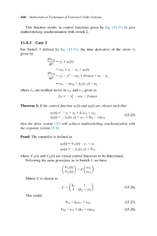
            For Switch 3 defined by Eq. (15.13), the time derivative of the errors is
            given by
                            q
                           d e 31
                                5 y 2 1 u 1 ðtÞ
                            dt q
                                5 e 32 1 x 1 2 x 3 1 u 1 ðtÞ
                            q
                           d e 32      3
                                5 y 1 2 y 2 αy 2 1 fcosωt 1 u 2 2 x 2
                                       1
                            dt q
                                5 e 31 2 αe 32 1 f 31 ðx; yÞ 1 u 2
            where f 13 are nonliear terms in e 11 and e 12 given as
                                         3
                                 f 13 52 y 2 αx 1 1 fcosωt
                                         1
            Theorem 3: If the control function u 1 ðtÞ and u 2 ðtÞ are chosen such that

                             u 1 ðtÞ 52 x 1 1 x 3 1 k 1 e 31 1 e 32
                                                                     ð15:25Þ
                             u 2 ðtÞ 52 f 13 ðx; yÞ 1 e 31 1 ðk 2 2 αÞe 32
            then the drive system 15.9 will achieve multiswitching synchronization with
            the response system 15.10
            Proof: The controller is defined as

                                  u 1 ðtÞ 5 V 31 ðtÞ 2 x 1 1 x 3
                                  u 2 ðtÞ 52 f 13 ðx; yÞ 1 V 32
            where V 31 ðtÞ and V 32 ðtÞ are virtual control functions to be determined.
               Following the same procedure as in Switch 1, we have

                                     V 31 ðtÞ    e 31
                                           5 C
                                     V 32 ðtÞ    e 32
               Matrix C is chosen as

                                        k 1    1
                                   C 5                               ð15:26Þ
                                         1  ðk 2 2 αÞ
               This yields
                                     V 31 5 k 1 e 31 1 e 32          ð15:27Þ

                                  V 32 5 e 31 1 ðk 2 2 αÞe 32        ð15:28Þ

