
Page 303 - Mechanical design of microresonators _ modeling and applications
P. 303
0-07-145538-8_CH06_302_08/30/05
Microcantilever and Microbridge Systems for Mass Detection
302 Chapter Six
1.2×10 - 20
1×10 - 20
8×10 - 21
∆m min 6×10 - 21
4×10 - 21
2×10 - 21
0
0 0.002 0.004 0.006 0.008 0.01
∆ω min
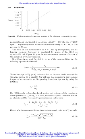
Figure 6.9 Minimum detected mass as a function of the minimum resonant frequency.
microcantilever constructed of polysilicon with E = í 170 GPa and ȡ = 2330
3
kg/m . The geometry of the microcantilever is defined by l = 100 m, w = 10
m, and t = 50 nm.
The mass of this micromember is m = 1.165 ng (nanograms), and its
bending resonant frequency is calculated by means of Eq. (2.68) as
Ȧ 0 = 433,979 rad/. Figure 6.9 plots the minimum added mass as a function of
the minimum frequency variation.
By differentiating Ȧ of Eq. (6.5) in terms of the mass addition ǻm, the
following equation is obtained:
1 k e
ǻȦ =– ǻm (6.10)
2 2
e/
k (m + ǻm)(m + ǻm)
e
e
The minus sign in Eq. (6.10) indicates that an increase in the mass of the
vibrating system by a quantity ǻm will lead to a decrease in the resonant
frequency by a quantity ǻȦ. By ignoring the minus sign and by using the
notation
ǻȦ
f = (6.11)
Ȧ
Ȧ
0
Eq. (6.10) can be reformulated and written just in terms of the nondimen-
sional parameters f m and f Ȧ . It is thus possible to express the mass fraction
as a function of the resonant frequency fraction in the form:
1 í 4 f (1 í f ) í 1 í 8 f (1 í f )
Ȧ
Ȧ
Ȧ
Ȧ
f m = 4 f (1 í f ) (6.12)
Ȧ
Ȧ
Conversely, the same equation enables us to express f Ȧ in terms of f m , namely,
1+ f m + 1+ f (4+ f )
m
m
f = 2(1+ f ) (6.13)
Ȧ
m
Downloaded from Digital Engineering Library @ McGraw-Hill (www.digitalengineeringlibrary.com)
Copyright © 2004 The McGraw-Hill Companies. All rights reserved.
Any use is subject to the Terms of Use as given at the website.