
Page 72 - Mechanical design of microresonators _ modeling and applications
P. 72
0-07-145538-8_CH02_71_08/30/05
Basic Members: Lumped- and Distributed-Parameter Modeling and Design
Basic Members: Lumped- and Distributed-Parameter Modeling and Design 71
1.04
1.03
1.02
sh
f b /f b
1.01
1
0 0.02 0.04 0.06 0.08 0.1
α
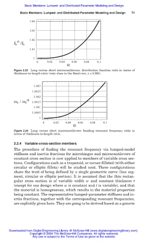
Figure 2.23 Long versus short microcantilevers: distribution function ratio in terms of
thickness-to-length ratio (very close to the fixed root, x = 0.99l).
1.003
1.0025
1.002
sh
ω b / ω b 1.0015
1.001
1.0005
1
0 0.02 0.04 0.06 0.08 0.1
α
Figure 2.24 Long versus short microcantilevers: bending resonant frequency ratio in
terms of thickness-to-length ratio.
2.2.4 Variable-cross-section members
The procedure of finding the resonant frequency via lumped-model
stiffness and inertia fractions for microhinges and microcantilevers of
constant cross section is now applied to members of variable cross sec-
tions. Configurations such as a trapezoid, or corner-filleted (with either
circular or elliptic fillets) will be studied next. These configurations
share the trait of being defined by a single geometric curve (line seg-
ment, circular or elliptic portion). It is assumed that the thin rectan-
gular cross section is of variable width w and constant thickness t
(except for one design where w is constant and t is variable), and that
the material is homogeneous, which results in the material properties
being constant. The representative lumped-parameter stiffness and in-
ertia fractions, together with the corresponding resonant frequencies,
are explicitly given here. They are going to be derived based on a generic
Downloaded from Digital Engineering Library @ McGraw-Hill (www.digitalengineeringlibrary.com)
Copyright © 2004 The McGraw-Hill Companies. All rights reserved.
Any use is subject to the Terms of Use as given at the website.