
Page 68 - Mechanical design of microresonators _ modeling and applications
P. 68
0-07-145538-8_CH02_67_08/30/05
Basic Members: Lumped- and Distributed-Parameter Modeling and Design
Basic Members: Lumped- and Distributed-Parameter Modeling and Design 67
15000
12500
10000
ω a,e / ω b,e
7500
5000
2500
0
0 0.0002 0.0004 0.0006 0.0008 0.001
α
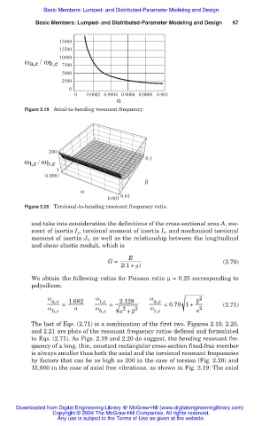
Figure 2.19 Axial-to-bending resonant frequency.
200
0.1
ω t,e / ω b,e
1
0.0001
β
α
0.01
0.001
Figure 2.20 Torsional-to-bending resonant frequency ratio.
and take into consideration the definitions of the cross-sectional area A, mo-
ment of inertia I y , torsional moment of inertia I t , and mechanical torsional
moment of inertia J t , as well as the relationship between the longitudinal
and shear elastic moduli, which is
E
G = (2.70)
2(1+ ȝ)
We obtain the following ratios for Poisson ratio Í = 0.25 corresponding to
polysilicon:
Ȧ Ȧ Ȧ 2
a,e = 1.682 t,e = 2.128 a,e =0.79 1+ ȕ (2.71)
Ȧ Į Ȧ 2 2 Ȧ 2
b,e b,e Į + ȕ t,e Į
The last of Eqs. (2.71) is a combination of the first two. Figures 2.19, 2.20,
and 2.21 are plots of the resonant frequency ratios defined and formulated
in Eqs. (2.71). As Figs. 2.19 and 2.20 do suggest, the bending resonant fre-
quency of a long, thin, constant rectangular cross-section fixed-free member
is always smaller than both the axial and the torsional resonant frequencies
by factors that can be as high as 200 in the case of torsion (Fig. 2.20) and
15,000 in the case of axial free vibrations, as shown in Fig. 2.19. The axial
Downloaded from Digital Engineering Library @ McGraw-Hill (www.digitalengineeringlibrary.com)
Copyright © 2004 The McGraw-Hill Companies. All rights reserved.
Any use is subject to the Terms of Use as given at the website.