
Page 64 - Mechanical design of microresonators _ modeling and applications
P. 64
0-07-145538-8_CH02_63_08/30/05
Basic Members: Lumped- and Distributed-Parameter Modeling and Design
Basic Members: Lumped- and Distributed-Parameter Modeling and Design 63
60
50
error [%] 40
30
20
10
0
0 0.2 0.4 0.6 0.8 1
t/w
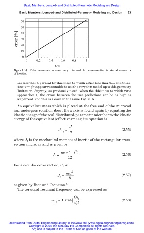
Figure 2.16 Relative errors between very thin and thin cross-section torsional moments
of inertia.
are less than 5 percent for thickness-to-width ratios less than 0.1, and there-
fore it might appear reasonable to use the very thin model up to this geometry
limitation. Anyway, as previously noted, when the thickness-to-width ratio
approaches 1, the errors between the two predictions can be as high as
60 percent, and this is shown in the same Fig. 2.16.
An equivalent mass which is placed at the free end of the microrod
and undergoes rotation about the x axis is found again by equating the
kinetic energy of the real, distributed-parameter microbar to the kinetic
energy of the equivalent (effective) mass; its equation is
J t
J = (2.55)
t,e 3
where J is the mechanical moment of inertia of the rectangular cross-
t
section microbar and is given by
2
2
m(w + t )
J = 12 (2.56)
t
For a circular cross section, J t is
2
md
J = 8 (2.57)
t
as given by Beer and Johnston. 8
The torsional resonant frequency can be expressed as
GI t
Ȧ =1.732 (2.58)
t,e J l
t
Downloaded from Digital Engineering Library @ McGraw-Hill (www.digitalengineeringlibrary.com)
Copyright © 2004 The McGraw-Hill Companies. All rights reserved.
Any use is subject to the Terms of Use as given at the website.