
Page 59 - Mechanical design of microresonators _ modeling and applications
P. 59
0-07-145538-8_CH02_58_08/30/05
Basic Members: Lumped- and Distributed-Parameter Modeling and Design
58 Chapter Two
J t,e
x
Figure 2.9 Effective inertia corresponding to free torsional vibrations of a fixed-free
microbar.
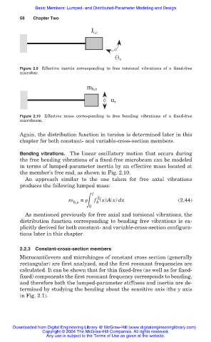
m b,e
u z
Figure 2.10 Effective mass corresponding to free bending vibrations of a fixed-free
microbeam.
Again, the distribution function in torsion is determined later in this
chapter for both constant- and variable-cross-section members.
Bending vibrations. The linear oscillatory motion that occurs during
the free bending vibrations of a fixed-free microbeam can be modeled
in terms of lumped-parameter inertia by an effective mass located at
the member’s free end, as shown in Fig. 2.10.
An approach similar to the one taken for free axial vibrations
produces the following lumped mass:
l
2
m b,e ฒ f (x)A(x) dx (2.44)
= ȡ
b
0
As mentioned previously for free axial and torsional vibrations, the
distribution function corresponding to bending free vibrations is ex-
plicitly derived for both constant- and variable-cross-section configura-
tions later in this chapter.
2.2.3 Constant-cross-section members
Microcantilevers and microhinges of constant cross section (generally
rectangular) are first analyzed, and the first resonant frequencies are
calculated. It can be shown that for thin fixed-free (as well as for fixed-
fixed) components the first resonant frequency corresponds to bending,
and therefore both the lumped-parameter stiffness and inertia are de-
termined by studying the bending about the sensitive axis (the y axis
in Fig. 2.1).
Downloaded from Digital Engineering Library @ McGraw-Hill (www.digitalengineeringlibrary.com)
Copyright © 2004 The McGraw-Hill Companies. All rights reserved.
Any use is subject to the Terms of Use as given at the website.