
Page 60 - Mechanical design of microresonators _ modeling and applications
P. 60
0-07-145538-8_CH02_59_08/30/05
Basic Members: Lumped- and Distributed-Parameter Modeling and Design
Basic Members: Lumped- and Distributed-Parameter Modeling and Design 59
l
t
w
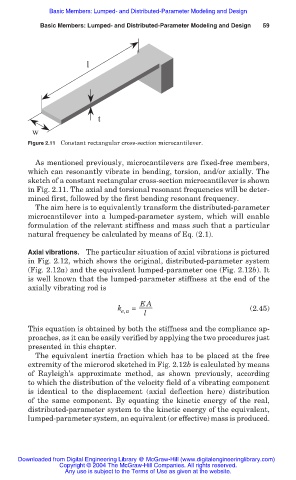
Figure 2.11 Constant rectangular cross-section microcantilever.
As mentioned previously, microcantilevers are fixed-free members,
which can resonantly vibrate in bending, torsion, and/or axially. The
sketch of a constant rectangular cross-section microcantilever is shown
in Fig. 2.11. The axial and torsional resonant frequencies will be deter-
mined first, followed by the first bending resonant frequency.
The aim here is to equivalently transform the distributed-parameter
microcantilever into a lumped-parameter system, which will enable
formulation of the relevant stiffness and mass such that a particular
natural frequency be calculated by means of Eq. (2.1).
Axial vibrations. The particular situation of axial vibrations is pictured
in Fig. 2.12, which shows the original, distributed-parameter system
(Fig. 2.12a) and the equivalent lumped-parameter one (Fig. 2.12b). It
is well known that the lumped-parameter stiffness at the end of the
axially vibrating rod is
EA
k e,a = l (2.45)
This equation is obtained by both the stiffness and the compliance ap-
proaches, as it can be easily verified by applying the two procedures just
presented in this chapter.
The equivalent inertia fraction which has to be placed at the free
extremity of the microrod sketched in Fig. 2.12b is calculated by means
of Rayleigh’s approximate method, as shown previously, according
to which the distribution of the velocity field of a vibrating component
is identical to the displacement (axial deflection here) distribution
of the same component. By equating the kinetic energy of the real,
distributed-parameter system to the kinetic energy of the equivalent,
lumped-parameter system, an equivalent (or effective) mass is produced.
Downloaded from Digital Engineering Library @ McGraw-Hill (www.digitalengineeringlibrary.com)
Copyright © 2004 The McGraw-Hill Companies. All rights reserved.
Any use is subject to the Terms of Use as given at the website.