
Page 56 - Mechanical design of microresonators _ modeling and applications
P. 56
0-07-145538-8_CH02_55_08/30/05
Basic Members: Lumped- and Distributed-Parameter Modeling and Design
Basic Members: Lumped- and Distributed-Parameter Modeling and Design 55
2
1.5
e k [%] 1
0.5
0
0 0.05 0.1 0.15 0.2
α
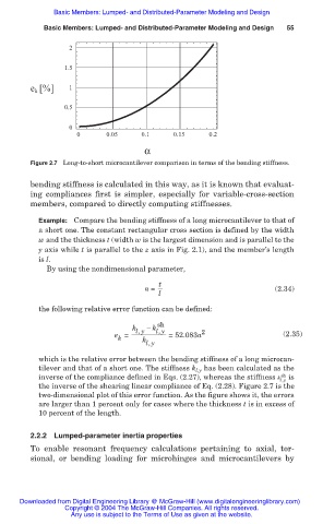
Figure 2.7 Long-to-short microcantilever comparison in terms of the bending stiffness.
bending stiffness is calculated in this way, as it is known that evaluat-
ing compliances first is simpler, especially for variable-cross-section
members, compared to directly computing stiffnesses.
Example: Compare the bending stiffness of a long microcantilever to that of
a short one. The constant rectangular cross section is defined by the width
w and the thickness t (width w is the largest dimension and is parallel to the
y axis while t is parallel to the z axis in Fig. 2.1), and the member’s length
is l.
By using the nondimensional parameter,
t
Į = (2.34)
l
the following relative error function can be defined:
sh
k l,y í k l,y
e = k l,y = 52.083Į 2 (2.35)
k
which is the relative error between the bending stiffness of a long microcan-
tilever and that of a short one. The stiffness k l,y has been calculated as the
sh
inverse of the compliance defined in Eqs. (2.27), whereas the stiffness k is
l,y
the inverse of the shearing linear compliance of Eq. (2.28). Figure 2.7 is the
two-dimensional plot of this error function. As the figure shows it, the errors
are larger than 1 percent only for cases where the thickness t is in excess of
10 percent of the length.
2.2.2 Lumped-parameter inertia properties
To enable resonant frequency calculations pertaining to axial, tor-
sional, or bending loading for microhinges and microcantilevers by
Downloaded from Digital Engineering Library @ McGraw-Hill (www.digitalengineeringlibrary.com)
Copyright © 2004 The McGraw-Hill Companies. All rights reserved.
Any use is subject to the Terms of Use as given at the website.