Page 65 - Mechanical design of microresonators _ modeling and applications
P. 65

0-07-145538-8_CH02_64_08/30/05


                                    Basic Members: Lumped- and Distributed-Parameter Modeling and Design

                              64   Chapter Two

                                   uz  (x)                                 mb,e
                                                    uz                             uz


                                                Fz
                                           x                            kb,e
                                       l

                                          (a)                        (b)
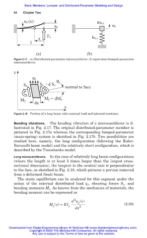
                              Figure 2.17 (a) Distributed-parameter microcantilever; (b) equivalent lumped-parameter
                              microcantilever.


                              z
                                        qz
                                                     θy
                                   Sz       Sz  + d Sz
                                                          normal to face


                                              My +  dMy
                                 My
                                         dx
                                                         x
                              Figure 2.18 Portion of a long beam with external load and internal reactions.

                              Bending vibrations.  The bending vibration of a microcantilever is il-
                              lustrated in Fig. 2.17. The original distributed-parameter member is
                              pictured in Fig. 2.17a whereas the corresponding lumped-parameter
                              (mass-spring) system is sketched in Fig. 2.17b. Two possibilities are
                              studied here,  namely, the long configuration (following the Euler-
                              Bernoulli beam model) and the relatively short configuration, which is
                              described by the Timoshenko model.
                              Long microcantilevers.  In the case of relatively long beam configurations
                              (where the length is at least 5 times larger than the largest cross-
                              sectional dimension), the tangent to the neutral axis is perpendicular
                              to the face, as sketched in Fig. 2.18, which pictures a portion removed
                              from a deformed (bent) beam.
                                The static equilibrium can be analyzed for this segment under the
                              action of the external distributed load  q z , shearing  forces  S z , and
                              bending moments M y . As known from the mechanics of materials, the
                              bending moment can be expressed as

                                                              2
                                                             d u (x)
                                                                 z
                                                 M (x) = EI y                            (2.59)
                                                   y
                                                               dx 2


                           Downloaded from Digital Engineering Library @ McGraw-Hill (www.digitalengineeringlibrary.com)
                                      Copyright © 2004 The McGraw-Hill Companies. All rights reserved.
                                        Any use is subject to the Terms of Use as given at the website.
   60   61   62   63   64   65   66   67   68   69   70