
Page 95 - Mechanical design of microresonators _ modeling and applications
P. 95
0-07-145538-8_CH02_94_08/30/05
Basic Members: Lumped- and Distributed-Parameter Modeling and Design
94 Chapter Two
The solution to Eq. (2.170) is of the form:
ș (x) = Acosh (r x) + B sinh (r x) + C cos (r x) + D sin (r x) (2.172)
y 1 1 2 2
4
4
4
4
2 Ȗ +4ȕ Ȗ 2 2 Ȗ +4ȕ + Ȗ 2
where r = 2 r = 2 (2.173)
1
2
The deflection is calculated from the first of Eqs. (2.169) as
3
r 1 Asinh (r x) + B cosh (r x)
1
1
3
+ r C sin (r x) í D cos (r x) (2.174)
2
2
2
u (x) =
z 4
ȕ
The natural frequencies of relatively short line members can be
determined by using specific boundary conditions for fixed-free beams
(microcantilevers) and fixed-fixed beams (microbridges), as indicated
for long line members. Numerical examples are not included here
contrasting the results provided by the long- and short-beam model
predictions, but it can easily be verified that small differences exist
between the two models’ bending-related resonant frequencies. This
topic was discussed earlier in this chapter by using lumped-parameter
models.
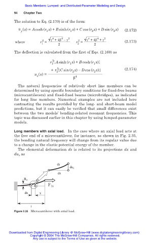
Long members with axial load. In the case where an axial load acts at
the free end of a microcantilever, for instance, as shown in Fig. 2.35,
the bending natural frequency will change from its regular value due
to a change in the elastic potential energy of the member.
The elemental deformation ds is related to its projections dx and
du as
z
ds
du z
dx
u z
F 1x
dx x
1
Figure 2.35 Microcantilever with axial load.
Downloaded from Digital Engineering Library @ McGraw-Hill (www.digitalengineeringlibrary.com)
Copyright © 2004 The McGraw-Hill Companies. All rights reserved.
Any use is subject to the Terms of Use as given at the website.