
Page 91 - Mechanical design of microresonators _ modeling and applications
P. 91
0-07-145538-8_CH02_90_08/30/05
Basic Members: Lumped- and Distributed-Parameter Modeling and Design
90 Chapter Two
2
2 4
ȡat 140ț E t (0.876b +8w )
1
2 2
+56țEGa t (10.4b +132w )
1
(2.154)
2 4
+G a (765.4b + 12,672w )
1
m sh =
b,e 2 2 2
3360(46a + țEt )
and this equation changes to the one defining a circularly filleted
microcantilever [Eq. (2.139)] when a ĺ R and b ĺ R.
The bending resonant frequency of a relatively short configuration
can be determined by means of Eqs. (2.151) and (2.154) and is not
explicitly given here.
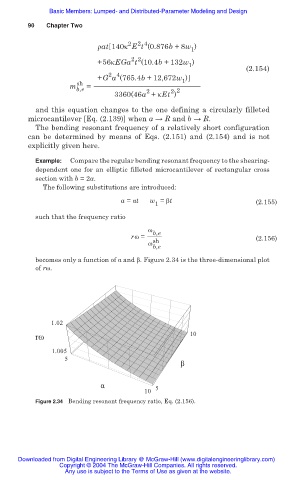
Example: Compare the regular bending resonant frequency to the shearing-
dependent one for an elliptic filleted microcantilever of rectangular cross
section with b = 2a.
The following substitutions are introduced:
a = Įt w = ȕt (2.155)
1
such that the frequency ratio
Ȧ b,e
rȦ = (2.156)
Ȧ sh
b,e
becomes only a function of Į and ȕ. Figure 2.34 is the three-dimensional plot
of rȦ.
1.02
rω 10
1.005
5
β
α 5
10
Figure 2.34 Bending resonant frequency ratio, Eq. (2.156).
Downloaded from Digital Engineering Library @ McGraw-Hill (www.digitalengineeringlibrary.com)
Copyright © 2004 The McGraw-Hill Companies. All rights reserved.
Any use is subject to the Terms of Use as given at the website.