
Page 87 - Mechanical design of microresonators _ modeling and applications
P. 87
0-07-145538-8_CH02_86_08/30/05
Basic Members: Lumped- and Distributed-Parameter Modeling and Design
86 Chapter Two
1.002
10
rk b
1
0.001
β
α
1
0.1
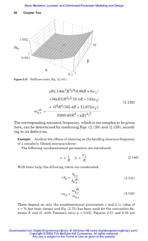
Figure 2.31 Stiffness ratio, Eq. (2.141).
2 4
2
ȡRt 140ț E t (0.88R +8w )
1
2 2
+56țEGR t (10.4R + 132w )
1
(2.139)
2
4
+ G R (765.4R + 12,672w )
sh 1
m b,e =
2 2
2
3360(4GR + țEt )
The corresponding resonant frequency, which is too complex to be given
here, can be determined by combining Eqs. (2.138) and (2.139), accord-
ing to its definition.
Example: Analyze the effects of shearing on the bending resonant frequency
of a circularly filleted microcantilever.
The following nondimensional parameters are introduced:
t w 1
Į = ȕ = (2.140)
R R
With their help, the following ratios are constructed:
k b,e
rk = (2.141)
b
k sh
b,e
sh
m b,e
rm = (2.142)
b
m
b,e
These depend on only the nondimensional parameters Į and ȕ [a value of
ț = ൣ has been chosen and Eq. (2.70) has been used for the connection be-
tween E and G, with Poisson’s ratio Í = 0.25]. Figures 2.31 and 2.32 are
Downloaded from Digital Engineering Library @ McGraw-Hill (www.digitalengineeringlibrary.com)
Copyright © 2004 The McGraw-Hill Companies. All rights reserved.
Any use is subject to the Terms of Use as given at the website.