
Page 84 - Mechanical design of microresonators _ modeling and applications
P. 84
0-07-145538-8_CH02_83_08/30/05
Basic Members: Lumped- and Distributed-Parameter Modeling and Design
Basic Members: Lumped- and Distributed-Parameter Modeling and Design 83
y
fixed
R φ
w
w 1
x
x
l = R
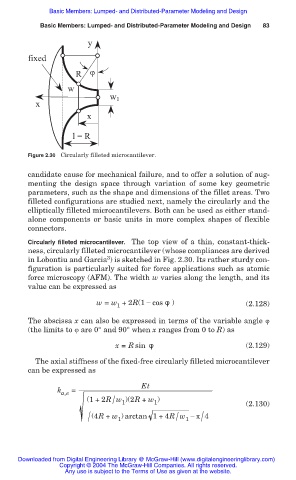
Figure 2.30 Circularly filleted microcantilever.
candidate cause for mechanical failure, and to offer a solution of aug-
menting the design space through variation of some key geometric
parameters, such as the shape and dimensions of the fillet areas. Two
filleted configurations are studied next, namely the circularly and the
elliptically filleted microcantilevers. Both can be used as either stand-
alone components or basic units in more complex shapes of flexible
connectors.
Circularly filleted microcantilever. The top view of a thin, constant-thick-
ness, circularly filleted microcantilever (whose compliances are derived
3
in Lobontiu and Garcia ) is sketched in Fig. 2.30. Its rather sturdy con-
figuration is particularly suited for force applications such as atomic
force microscopy (AFM). The width w varies along the length, and its
value can be expressed as
w = w +2R(1 í cos ́ ) (2.128)
1
The abscissa x can also be expressed in terms of the variable angle ij
(the limits to ij are 0° and 90° when x ranges from 0 to R) as
x = R sin ́ (2.129)
The axial stiffness of the fixed-free circularly filleted microcantilever
can be expressed as
Et
k =
a,e
/
(1+2R w )(2R + w ) (2.130)
1
1
1 /
/ (4R + w ) arctan 1+4R w íʌ 4
/
1
Downloaded from Digital Engineering Library @ McGraw-Hill (www.digitalengineeringlibrary.com)
Copyright © 2004 The McGraw-Hill Companies. All rights reserved.
Any use is subject to the Terms of Use as given at the website.