
Page 81 - Mechanical design of microresonators _ modeling and applications
P. 81
0-07-145538-8_CH02_80_08/30/05
Basic Members: Lumped- and Distributed-Parameter Modeling and Design
80 Chapter Two
1.3
20
rk b
1
2
β
α 10
10
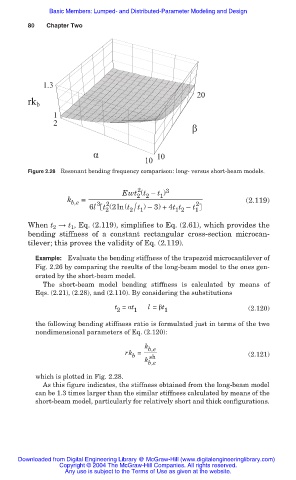
Figure 2.28 Resonant bending frequency comparison: long- versus short-beam models.
2
Ewt (t — t ) 3
1
2 2
k b,e = (2.119)
3 2
6l t (2ln(t t ) —3) +4t t — t 2
2 2/ 1 1 2 1
When t 2 ĺ t 1 , Eq. (2.119), simplifies to Eq. (2.61), which provides the
bending stiffness of a constant rectangular cross-section microcan-
tilever; this proves the validity of Eq. (2.119).
Example: Evaluate the bending stiffness of the trapezoid microcantilever of
Fig. 2.26 by comparing the results of the long-beam model to the ones gen-
erated by the short-beam model.
The short-beam model bending stiffness is calculated by means of
Eqs. (2.21), (2.28), and (2.110). By considering the substitutions
t = Įt l = ȕt
2 1 1 (2.120)
the following bending stiffness ratio is formulated just in terms of the two
nondimensional parameters of Eq. (2.120):
k b,e
rk =
b sh (2.121)
k
b,e
which is plotted in Fig. 2.28.
As this figure indicates, the stiffness obtained from the long-beam model
can be 1.3 times larger than the similar stiffness calculated by means of the
short-beam model, particularly for relatively short and thick configurations.
Downloaded from Digital Engineering Library @ McGraw-Hill (www.digitalengineeringlibrary.com)
Copyright © 2004 The McGraw-Hill Companies. All rights reserved.
Any use is subject to the Terms of Use as given at the website.