Page 83 - Mechanical design of microresonators _ modeling and applications
P. 83

0-07-145538-8_CH02_82_08/30/05


                                    Basic Members: Lumped- and Distributed-Parameter Modeling and Design

                              82   Chapter Two


                                     1.04
                              rm b                                              1.25

                                      1.01
                                   0.00001
                                                                              α


                                               t 1 [m]               1.05
                                                             0.00005
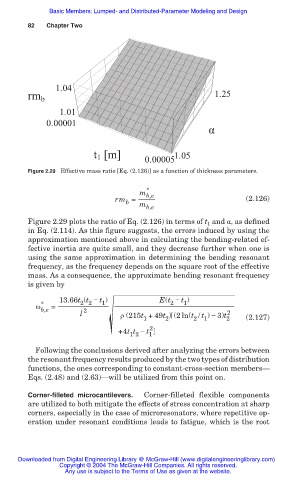
                              Figure 2.29 Effective mass ratio [Eq. (2.126)] as a function of thickness parameters.


                                                            m * b,e
                                                     rm =                               (2.126)
                                                        b   m b,e
                              Figure 2.29 plots the ratio of Eq. (2.126) in terms of t 1  and Į, as defined
                              in Eq. (2.114). As this figure suggests, the errors induced by using the
                              approximation mentioned above in calculating the bending-related ef-
                              fective inertia are quite small, and they decrease further when one is
                              using the same approximation in determining the bending resonant
                              frequency, as the frequency depends on the square root of the effective
                              mass. As a consequence, the approximate bending resonant frequency
                              is given by
                                      13.66t (t í t )            E(t í t )
                                                                        1
                                                                    2
                                            2 2
                                                  1
                                Ȧ * b,e  =   2
                                            l          ȡ (215t +49t ) (2ln(t / t ) í 3)t 2 2  (2.127)
                                                             1
                                                                             1
                                                                          2
                                                                   2
                                                      +4t t í t 1 2
                                                         1 2
                                Following the conclusions derived after analyzing the errors between
                              the resonant frequency results produced by the two types of distribution
                              functions, the ones corresponding to constant-cross-section members–
                              Eqs. (2.48) and (2.63)–will be utilized from this point on.
                              Corner-filleted microcantilevers.  Corner-filleted flexible components
                              are utilized to both mitigate the effects of stress concentration at sharp
                              corners, especially in the case of microresonators, where repetitive op-
                              eration under resonant conditions leads to fatigue, which is the root


                           Downloaded from Digital Engineering Library @ McGraw-Hill (www.digitalengineeringlibrary.com)
                                      Copyright © 2004 The McGraw-Hill Companies. All rights reserved.
                                        Any use is subject to the Terms of Use as given at the website.
   78   79   80   81   82   83   84   85   86   87   88