
Page 88 - Mechanical design of microresonators _ modeling and applications
P. 88
0-07-145538-8_CH02_87_08/30/05
Basic Members: Lumped- and Distributed-Parameter Modeling and Design
Basic Members: Lumped- and Distributed-Parameter Modeling and Design 87
1.0006
10
rm b
1
0.001
β
α
0.1 1
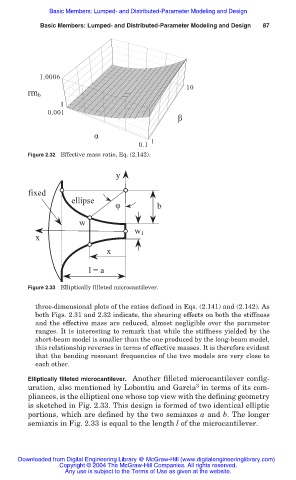
Figure 2.32 Effective mass ratio, Eq. (2.142).
y
fixed
ellipse
φ b
w
w 1
x
x
l = a
Figure 2.33 Elliptically filleted microcantilever.
three-dimensional plots of the ratios defined in Eqs. (2.141) and (2.142). As
both Figs. 2.31 and 2.32 indicate, the shearing effects on both the stiffness
and the effective mass are reduced, almost negligible over the parameter
ranges. It is interesting to remark that while the stiffness yielded by the
short-beam model is smaller than the one produced by the long-beam model,
this relationship reverses in terms of effective masses. It is therefore evident
that the bending resonant frequencies of the two models are very close to
each other.
Elliptically filleted microcantilever. Another filleted microcantilever config-
3
uration, also mentioned by Lobontiu and Garcia in terms of its com-
pliances, is the elliptical one whose top view with the defining geometry
is sketched in Fig. 2.33. This design is formed of two identical elliptic
portions, which are defined by the two semiaxes a and b. The longer
semiaxis in Fig. 2.33 is equal to the length l of the microcantilever.
Downloaded from Digital Engineering Library @ McGraw-Hill (www.digitalengineeringlibrary.com)
Copyright © 2004 The McGraw-Hill Companies. All rights reserved.
Any use is subject to the Terms of Use as given at the website.