
Page 159 - Mechanical Engineer's Data Handbook
P. 159
148 MECHANICAL ENGINEER’S DATA HANDBOOK
4.2 Flow of liquids in pipes and ducts
The Bernoulli equation states that for a fluid flowing in The ‘continuity equation’ is given as are expressions
a pipe or duct the total energy, relative to a height for the Reynold’s number, a non-dimensional quantity
datum, is constant if there is no loss due to friction. The expressing the fluid velocity in terms of the size of pipe,
formula can be given in terms of energy, pressure or etc., and the fluid density and viscosity.
‘head’.
4.2. I Bernoulli equation
Symbols used:
p = pressure
p = density If p1 =pz (incompressible fluid), then:
h = height above datum A,V,=A,V, or Q1=Q2
V=velocity where Q = volume flow rate
A = area
4.2.3 Reynold’s number
For an incompressible fluid p is constant, also the (non-dimensional velocity)
energy at 1 is the same as at 2, i.e.
E, = E, In the use of models, similarity is obtained, as far as
or pI/p+ V:/2+gh,=p,p+ V:/2+ghZ+Energy loss fluid friction is concerned, when:
(per kilogram)
VD
VD
In terms of pressure: Reynold’s number Re = p - = -
p1 + p v:/2 + pgh, =p2 + p ~:/2 + pgh, + Pressure losses P ”
In terms of ‘head’: is the same for the model and the full scale version.
pl/pg + v:/2g + h, =p,/pg + Vi/2g + h, +Head losses For a circular pipe:
Velocity pressure p, = p v2/2 D =diameter
p = dynamic viscosity
Velocity head h, = V2/2g v = kinematic viscosity
Pressure head h, = p/pg
For a non-circular duct:
4x Area 4A
-_
D = equivalen?.diameter = -
Perimeter P
Types of flow
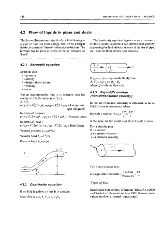
4.2.2 Continuity equation
In a circular pipe the flow is ‘laminar’ below Re N 2000
If no fluid is gained or lost in a conduit:
and ‘turbulent’ above about Re = 2500. Between these
Mass flow m=p,A,V,=p,A,V, values the flow is termed ‘transitional’.