
Page 161 - Mechanical Engineer's Data Handbook
P. 161
150 MECHANICAL ENGINEER’S DATA HANDBOOK
lo00 x 0.5 x 0.05 Pressure loss pr = pr + pf2 +
Reynold’s number Re = a.5 x 104
0.001
0.1
Relative roughness k/D =- = 0.002
50
Friction factor (from chart)f= 0.0073
The mass flow rate is the same in all pipes, i.e.
Pressure loss m=m -m -
- 2-etc.
1000~0.5~
1
pf =4 x 0.0073 x - =73N m-2 where: ml=pAIVl, etc. kgs-’
x
0.05 2
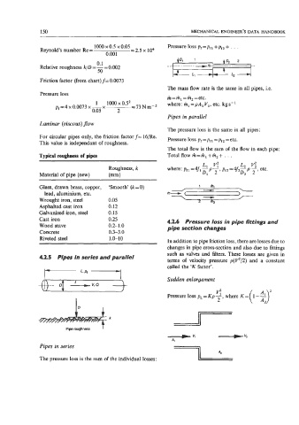
Pipes in parallel
Laminar (oiscous) flow
The pressure loss is the same in all pipes:
For circular pipes only, the friction factor f= 16/Re. Pressure loss pr = pr = pf2 = etc.
This value is independant of roughness.
The total flow is the sum of the flow in each pipe:
Typical roughness of pipes Total flow m=hl+m2+. . .
Ll
L2
Roughness, k where: pf1=4fl-p---, v: pf2=4f2-p-. v: etc.
Material of pipe (new) (mm) Dl 2 D2 2
Glass, drawn brass, copper, ‘Smooth’ (k -0)
lead, aluminium, etc.
Wrought iron, steel 0.05
Asphalted cast iron 0.12
Galvanized iron, steel 0.15
Cast iron 0.25 4.2.6 Pressure loss in pipe fittings and
Wood stave 0.2-1.0 pipe section changes
Concrete 0.3-3.0
Riveted steel 1.0-10
In addition to pipe friction loss, there are losses due to
changes in pipe cross-section and also due to fittings
such as valves and filters. These losses are given in
4.2.5 Pipes in series and parallel
terms of velocity pressure p(v2/2) and a constant
called the ‘K factor’.
I I Sudden enlargement
v:
Pressure loss pL = Kp -, where K =
2
ID I
h
Piperoughness I
Pipes in series
The pressure loss is the sum of the individual losses: