
Page 165 - Mechanical Engineer's Data Handbook
P. 165
154 MECHANICAL ENGINEER’S DATA HANDBOOK
Channels
Symbols used :
m = hydraulic mean radius = A/P
i=slope of channel Values of K
C = constant = 87/[ 1 + (K/&)]
A=flow area Surface K
P = wetted perimeter
Mean velocity V= ~Jmr Clean smooth wood, brick, stone 0.16
0.28
Dirty wood, brick, stone
Natural earth 1.30
Flow rate Q= VA
Maximum discharge for given excavation
Channel Condition Arrangement
Rectangular d=b/2
Trapezoidal Sides tangential to
semicircle
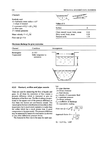
Let :
4.3.3 Venturi, orifice and pipe nozzle
D = pipe diameter
d = throat diameter
These are used for measuring the flow of liquids and
p = fluid density
gases. In all three the restriction of flow creates a p, =density of manometer fluid
pressure difference which is measured to give an p1 =upstream pressure
indication of the flow rate. The flow is always propor- p = throat pressure
tional to the square root of the pressure difference so C, = coefficient of discharge
that these two factors are non-linearly related. The h = manometer reading
venturi gives the least overall pressure loss (this is often
important), but is much more expensive to make than Flow rate Q = C,E 4 /?
the orifice which has a much greater loss. A good
compromise is the pipe nozzle. The pressure difference
may be measured by means of a manometer (as shown)
or any other differential pressure device.
The formula for flow rate is the same for each type.