
Page 179 - Mechanical Engineer's Data Handbook
P. 179
168 MECHANICAL ENGINEER’S DATA HANDBOOK
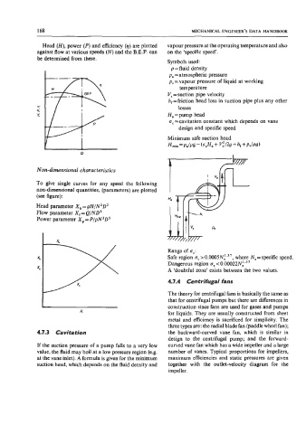
Head (H), power (P) and efficiency (q) are plotted vapour pressure at the operating temperature and also
against flow at various speeds (N) and the B.E.P. can on the ‘specific speed’.
be determined from these.
Symbols used:
p=fluid density
pa = atmospheric pressure
p, = vapour pressure of liquid at working
temperature
V, =suction pipe velocity
h, = friction head loss in suction pipe plus any other
losses
Ha =pump head
u, =cavitation constant which depends on vane
design and specific speed
Minimum safe suction head
Hmin=Pa/Pg-(ocHa+ C/2g+hr+Pv/Pg)
0
Non-dimensional characteristics
To give single curves for any speed the following
non-dimensional quantities, (parameters) are plotted
(see figure):
Head parameter X,=gH/N2DZ
Flow parameter X, = Q/ND3
Power parameter X,= PIpN3DS
Range of 6,:
Safe region u, >0.0005Nf.37, where N,=specific speed.
Dangerous region u, < O.OOO~~N:.~’
A ‘doubtful zone’ exists between the two values.
4.7.4 Centrifugal fans
The theory for centrifugal fans is basically the same as
that for centrifugal pumps but there are differences in
construction since fans are used for gases and pumps
for liquids. They are usually constructed from sheet
metal and efficiency is sacrificed for simplicity. The
three types are: the radial blade fan (paddle wheel fan);
4.7.3 Cavitation the backward-curved vane fan, which is similar in
design to the centrifugal pump; and the forward-
If the suction pressure of a pump falls to a very low curved vane fan which has a wide impeller and a large
value, the fluid may boil at a low pressure region (e.g. number of vanes. Typical proportions for impellers,
at the vane inlet). A formula is given for the minimum maximum efficiencies and static pressures are given
suction head, which depends on the fluid density and together with the outlet-velocity diagram for the
impeller.