
Page 182 - Mechanical Engineer's Data Handbook
P. 182
170 MECHANICAL ENGINEER’S DATA HANDBOOK
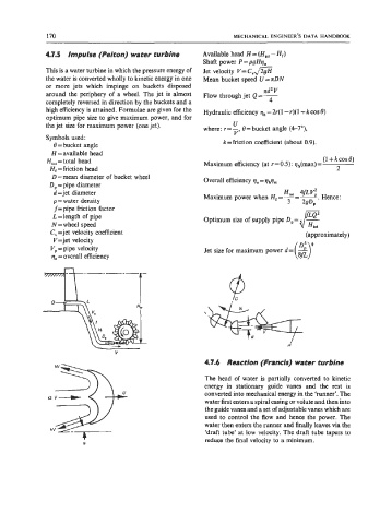
4.7.5 Impulse (Pelton) water turbine Available head H = (HIoI - H,)
Shaft power P = pgHq,
This is a water turbine in which the pressure energy of Jet velocity V=C,m
the water is converted wholly to kinetic energy in one Mean bucket speed U = nDN
or more jets which impinge on buckets disposed
nd2 V
around the periphery of a wheel. The jet is almost Flow through jet Q=- 4
completely reversed in direction by the buckets and a
high efficiency is attained. Formulae are given for the Hydraulic efficiency qh = 2r( 1 -I)( 1 + k cos 0)
optimum pipe size to give maximum power, and for
U
the jet size for maximum power (one jet). where: r = -, 0 =bucket angle (4-7”),
Symbols used: V
8 =bucket angle k =friction coefficient (about 0.9).
H = available head
H,,, = total head Maximum efficiency (at r = 0.5): qh(max) = (1 + k cos 8)
H, = friction head 2
D = mean diameter of bucket wheel
D, = pipe diameter Overall efficiency qo = qhqm
d =jet diameter HtOI 4ftv2 Hence:
p = water density Maximum power when Hr=-=L.
3
29Dp
f= pipe friction factor
L=length of pipe Optimum size of supply pipe D,= F
-
N = wheel speed
C, =jet velocity coefficient (approximately)
V=jet velocity
(z)’
V, = pipe velocity Jet size for maximum power d = -
qo = overall efficiency
T------l-
H
V
4.7.6 Reaction (Francis) water turbine
The head of water is partially converted to kinetic
energy in stationary guide vanes and the rest is
converted into mechanical energy in the ‘runner’. The
water first enters a spiral casing or volute and then into
the guide vanes and a set of adjustable vanes which are
used to control the flow and hence the power. The
water then enters the runner and finally leaves via the
‘draft tube’ at low velocity. The draft tube tapers to
reduce the final velocity to a minimum.
R