
Page 185 - Mechanical Engineer's Data Handbook
P. 185
MANUFACTURING TECHNOLOGY 173
~~
5.2 Turning
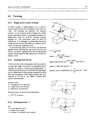
5.2. I Single point metal cutting
In metal cutting, a wedge-shaped tool is used to
remove material from the workpiece in the form of a
‘chip’. Two motions are required: the ‘primary
motion’, e.g. the rotation of the workpiece in a lathe;
and the ‘secondary motion’,e.g. the feed ofa lathe tool.
Single-point tools are used for turning, shaping,
planing, etc., and multi-point tools are used for
milling, etc. It is necessary to understand the forces
acting on the tool and their dects on power require-
ment, tool life and production cost.
In the following tables of tool forces and formulae
specific power consumption, metal removal rate, tool V
life, etc., are given. A graph shows the tool life plotted P = F, - (watts)
60
against cutting speed for high-speed steel, carbide and
ceramic tools. where: v= x(D -d)N (m min - ’ )
lo00
5.2.2 Cutting tool forces n(D-d)d fN
Metal removal rate Q = lo00 (an3 min-’)
Tool forces vary with cutting speed, feed rate, depth of
cut and rake angle. Force may be measured experi- where: f=feed rate (mm rev-’).
mentally by using a ‘cutting tool dynamometer’ in P
which the tool is mounted on a flexible steel diaphragm Specific power consumption P,=- (wattscrr-3 min-
and its deflections in three planes measured by three Q
electrical transducers. Three meters indicate the force,
typically of 25 N up to, say, 2000 N. Graphs show
typical characteristics.
Symbols used:
F, =cutting force (in newtons)
F, = radial force (in newtons)
F,=feed force (in newtons)
Resultant force on tool in horizontal plane
= Jm: newtons
5.2.3 Cutting power, P
Let:
D = work diameter (mm)
d-depth of cut (mm)
N = number of revolutions per minute