
Page 189 - Mechanical Engineer's Data Handbook
P. 189
MANUFACTURING TECHNOLOGY 177
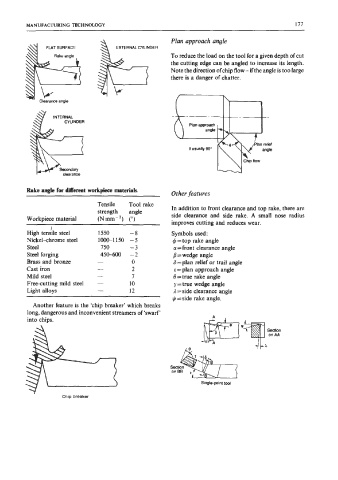
Plan approach angle
EXTERNAL CYLINDER
FLAT SURFACE EXTERNAL CYLINDER
To reduce the load on the tool for a given depth of cut
the cutting edge can be angled to increase its length.
Note the direction of chip flow - if the angle is too large
there is a danger of chatter.
k
Clearance angle
Clearance angle
INTERNAL
CYLINDER Plan approach
angle
e usually 90"
I Chip now
IC clearance
Rake angle for Merent workpiece materials
Other features
Tensile Tool rake
strength angle In addition to front clearance and top rake, there are
side clearance and side rake. A small nose radius
Workpiece material (Nmm-2) (")
improves cutting and reduces wear.
I
High tensile steel 1550 -8 Symbols used:
Nickel-chrome steel loo(r1150 -5 4-top rake angle
Steel 750 -3 a =front clearance angle
Steel forging 450-600 -2 /3 = wedge angle
Brass and bronze - 0 S =plan relief or trail angle
Cast iron - 2 E = plan approach angle
Mild steel - 7 8 =true rake angle
Free-cutting mild steel - 10 y = true wedge angle
Light alloys - 12 1 =side clearance angle
$ =side rake angle.
Another feature is the 'chip breaker' which breaks
long, dangerous and inconvenient streamers of 'swarf'
into chips.
Single-point tool
Chip breaker