
Page 36 - Mechanical Engineer's Data Handbook
P. 36
STRENGTHS OF MATERIALS 25
1.4.1 Beoms - &sic theory
X
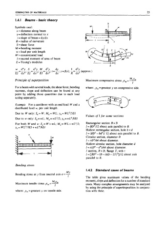
Symbols used:
x = distance along beam
y = deflection normal to x
i = slope of beam = dy/dx
R = radius of curvature
S = shear force
M = bending moment
w = load per unit length
W=concentrated load
I = second moment of area of beam
E = Young’s modulus
w d4y S d’y M d2y dy 1 d2y
-=-. -=-. -=-. i=-; y=f(x); -=- (approx.)
El dx4’ El dx3’ El dx2’ dx R dx2
McYm
Principle of superposition Maximum compressive stress p, = -
I
For a beam with several loads, the shear force, bending where: = greatat Y on compressive side,
moment, slope and deflection can be found at any
point by adding those quantities due to each load .C~/~~-JM
acting separately.
Example For a cantilever with an end load Wand a
distributed load w, per unit length.
Due to W only: Sa= W, Ma= WL; y,= WL’I3EI
Values of I for some sections
Due to w only: S,=wL; M,=wL2/2; y,=wL4/8EI
For both Wand w: Sa= W+wL; Ma= WL+wL2/2; Rectangular section Bx
y,= WL3/3EI +wL4/8E1 1 = BD3/12 about axis parallel to B.
Hollow rectangular section, hole b x d
1 = (BD3- bd3)/ 12 about axis parallel to B.
Circular section, diameter D
I = rrD4/64 about diameter.
Hollow circular section, hole diameter d
1 = n(D4 -d4)/64 about diameter.
I section, B x D, flange T, web t
I = [BD’ - (B-t)(D- 2T)3]/12 about axis
parallel to B.
Bending stress
I .4.2 Standard cases of beams
MY
Bending stress at y from neutral axis c=-
I The table gives maximum values of the bending
Ma,
Maximum tensile stress p, = - moment, slope and deflection for a number of standard
cases. Many complex arrangements may be analysed
I
by using the principle of superimposition in conjunc-
where: ,ym = greatest y on tensile side. tion with these.