Page 38 - Mechanical Engineer's Data Handbook
P. 38

STRENGTHS OF  MATERIALS                                                           27

                                         3  -             -                     7  -
                                                           1
                                         16               32                    768
                                         at wall          at prop               at load
                                                                                (not maximum)
                                     sw
                                     16

                                                           1
                                         1
                                         -                -                     0.0054
                                         8                48
                                         at wall          at prop               0.57851, from wall
                                   3w
                                    8


         I A.3   Continuous beams                    n Spans:
                                                     Apply to each group of three supports to obtain (n - 2)
         Most beam problems are concerned with a single span.   simultaneous equations which can  be solved to give
         Where there are two or more  spans the  solution  is   the (n - 2) unknown bending moments.
         more complicated and the following method is used.
         This uses the so-called ‘equation of three moments’ (or   Solution  :
                                                     For cases (2) and (3). If M, and M3 are known (these
         Clapeyron’s equation), which is applied to two spans   are either zero or due to an overhanging load), then
         at a time.
                                                     M, can be found. See example.
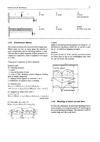
         Clapeyron’s equation of  three moments
         Symbols used:
         M = bending moment                            “Free EM’ diabram    I
          L =span
          I = second moment of  area
          A =area  of  ‘free’ bending moment  diagram  treating
         span as simply supported
         %=distance from support to centroid C of  A
         y=deflections  of  supports due to loading
         (1)  General case:
         MI LlIIl+2M,(Ll/11  +L,l~z)+M3L,II, =         P+4-
          6(Aixi/LiIi + A,x,/LzIz)+  6Eb2IL1 + (YZ -Y~)/LzI
         (2)  Supports at same level, same I:                     Resultam  BM  diagram
         Yl =YZ=Y3=’
         MIL1 +2M,(L1 +L,)+ M,L, =6(A,x,/L1+ AZxJZ-2)
                                          (usual case)
         (3) Free ends, Ml=M3=O:                     I A4  Bending of thick curved bars
         M2(4 + &)=3(A,xJb+  &41,2)
                                                     In these the calculation of  maximum bending stress is
                                                     morecomplex, involving the quantity h2 which is given
                                                     for several geometrical shapes. The method is used for
                                                     loaded rings and the crane hook.

           Yl         Y2          Y3
   33   34   35   36   37   38   39   40   41   42   43