
Page 43 - Mechanical Engineer's Data Handbook
P. 43
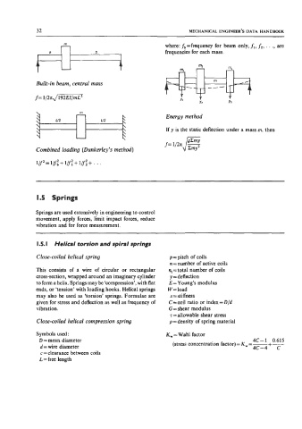
32                                                  MECHANICAL ENGINEER’S DATA  HANDBOOK

                       rn                                where: &=frequency  for  beam  only, f,, f2, . . ., are
                  a              b                       frequencies for each mass.
              I

                                                                    m2
                                                                   3          rn3
                                                              m1
                                                                       ---
             Built-in beam, central mass                                 rn
             f= 1/2nJEEi7iZ
                                                              Yl
                                                                    Y2        Y3
                                                         Energy method

                                                         If  y  is the static deflection under a mass m, then


             Combined loading  (Dunkerley’s method)

             l/y= + 1fl:  + 11: + . . .
                  1/f:


             1.5  Springs

             Springs are used extensively in engineering to control
             movement, apply forces, limit impact forces, reduce
             vibration and for force measurement.


             I .5. I  Helical torsion and spiral springs

             Close-coiled  helical spring                 p=pitch  of coils
                                                          n = number of active coils
             This  consists  of  a  wire  of  circular  or  rectangular   n,=total  number of  coils
             cross-section, wrapped around an imaginary cylinder   y = deflection
             to form a helix. Springs may be ‘compression’, with flat   E =Young’s  modulus
             ends, or ‘tension’ with loading hooks. Helical springs   W=load
             may  also be  used  as ‘torsion’ springs. Formulae are   s =stiffness
             given for stress and deflection as well as frequency of   C = coil ratio or index = D/d
             vibration.                                   G = shear modulus
                                                          7 =allowable  shear stress
             Close-coiled  helical compression spring     p =density  of spring material

             Symbols used:                               K, = Wahl factor
              D = mean diameter                                                       4C-1  0.615
                                                                                            +
                                                                                       4c-4  c
              d = wire diameter                            (stress concentration factor) = K, = - -
              c = clearance between coils
              L = free length