
Page 45 - Mechanical Engineer's Data Handbook
P. 45
34 MECHANICAL ENGINEER’S DATA HANDBOOK
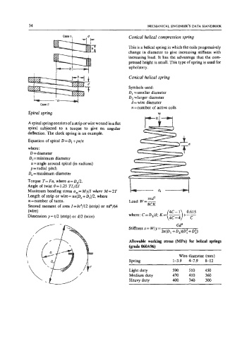
Case 1, .d Conical helical compression spring
This is a helical spring in which the coils progressively
change in diameter to give increasing stiffness with
increasing load. It has the advantage that the com-
pressed height is small. This type of spring is used for
upholstery.
Conical helical spring
Symbols used:
D, =smaller diameter
D, =larger diameter
d = wire diameter
case 2
n = number of active coils
Spiral spring W
A spiral spring consists of a strip or wire wound in a flat
spiral subjected to a torque to give an angular
deflection. The clock spring is an example.
Equation of spiral D = D, + pu/x
where:
D =diameter
Di = minimum diameter
u=angle around spiral (in radians)
p = radial pitch
Do = maximum diameter
Torque T= Fa, where a=DJ2.
Angle of twist 8= 1.25 TL/EI
Maximum bending stress om= My11 where M = 2T
Length of strip or wire = m(D0 + Di)/2, where md2
n = number of turns. Load W=-
Second moment of area I=bt3/12 (strip) or nd4/64 8CK
(wire) 4C-1 0.615
+ c
Dimension y = t/2 (strip) or d/2 (wire) where: C=D,/d; K= -
(4c - 4)
Allowable working stress (MPa) for helical springs
(grade MA%)
Wire diameter (mm)
Spring 1-3.9 4-7.9 8-12
Light duty 590 510 450
Medium duty 470 410 360
Heavy duty 400 340 300